MXW Microflex® Wireless Shure Microflex Wireless (MXW) system guide Version: 7.
Shure Incorporated Table of Contents MXW Microflex® Wireless 4 IMPORTANT SAFETY INSTRUCTIONS 4 Overview 4 General Description 5 Features 5 MXW Wireless System 7 Shure SystemOn Software For Managing Large Systems 5 0 High Density Mode 50 Configurations: Managing Multiple Groups 50 Wireless Management 51 Overview of Channel Coordination 51 Scanning Available RF Spectrum 52 PHS Detection 53 10 Identifying PHS Detection Errors 53 Audio Network Interface (ANI) 10 Setting RF Power 5
Shure Incorporated Transmitter Output Power 92 Wiring Diagram 93 WARNING Important Product Information Safety Information 94 SAFETY PRECAUTIONS 94 WARNING 94 Information to the user 95 95 95 Certifications 96 Trademarks 97 3/97
Shure Incorporated MXW Microflex® Wireless IMPORTANT SAFETY INSTRUCTIONS 1. 2. 3. 4. 5. 6. 7. 8. 9. 10. 11. 12. READ these instructions. KEEP these instructions. HEED all warnings. FOLLOW all instructions. DO NOT use this apparatus near water. CLEAN ONLY with dry cloth. DO NOT block any ventilation openings. Allow sufficient distances for adequate ventilation and install in accordance with the manufacturer’s instructions.
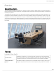
Shure Incorporated Overview General Description The Shure Microflex Wireless Series (MXW) is a complete microphone solution for flexible meeting rooms and boardrooms. It features automatic RF channel management, rechargeable wireless microphones with encryption (AES256), and digital audio networking using Dante™. The MXW Access Point (APT) mounts to a ceiling or wall for discreet communication between the wireless microphones and the digital audio network.
Shure Incorporated from the control software (battery runtime, time to full charge, charge cycle count and battery capacity). Discreet, Professional De sign Modern, lowprofile wireless microphone designs elegantly integrate into diverse AV environ ments. By eliminating wires, MXW noticeably reduces clutter and provides professional ele gance.
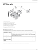
Shure Incorporated MXW Wireless System ① Wireless Microphones ② System processor and wireless transceiver ③ Microphone linking and charging station ④ Analog output device with gigabit network switch ⑤ Shielded Cat5e cables (not included) Components of the MXW System Microphone Transmitters MXW microphones transmit an encrypted, wireless audio signal to the access point. Four form factors are available: Hybrid Bodypack (MXW1) The bodypack secures to a belt or strap for hands-free, mobile communication.
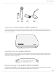
Shure Incorporated Access Point Transceiver (MXWAPT2, MXWAPT4, MXWAPT8) The Access Point Transceiver (2, 4 and 8 channel units) mounts to a wall or ceiling to manage encrypted, wireless audio con nections with microphones. As a system hub, it transports digital audio between the wireless microphones and other Dante de vices on the same network.
Shure Incorporated Note: The MXWNCS2 does not work with the MXW8 gooseneck microphones. MXW Control Software The MXW control software offers comprehensive remote control of key setup, monitoring and management functions. System Design and Technology Technology Overview of the Audio Path The MXW System combines Shure legendary audio quality with advanced digital networking technology.
Shure Incorporated Digital Audio Network The access point receives wireless audio from the microphones and distributes it to the audio network interface. • Low latency, tight clock synchronization, and high Quality-of-Service (QoS) provide reliable audio transport. • Digital audio is carried over Ethernet cables and standard IP equipment. • Audio coexists safely on the same network as IT and control data, or can be configured to use a dedicated network.
Shure Incorporated Converts digital network audio to an analog output for each channel. When associated to an MXW group, access point channels are automatically routed to the outputs of the ANI. ③ Channel Selector Selects a channel to perform the following functions: Action Function Single Press Listen to that channel at the headphone jack Display and adjust the channel output level and attenuation Monitor output signal on the level meter Press and Hold (3 sec onds) Mute/unmute a channel.
Shure Incorporated Indicate the status of the hardware: LED Color Status Power Green Unit is powered on. Ethernet Green Connected to an Ethernet device. Green All connected receive channels are OK (receiving digital audio as expected). Flashing Green One or more connected receive channels experiencing a subscription error or is un resolved (transmitting device is off, disconnected, renamed or has incorrect network setting).
Shure Incorporated Note: This input is meant for balanced connection. If an unbalanced source is used, such as an IPOD or MP3 player, only use pins 1 (signal) and 3 (ground) of the block connector. See Specifications sections for wiring diagrams. ⑥ Reset Button Press and hold the button for five seconds to reboot the device with factory default settings.
Shure Incorporated MXWAPT2 Two-channel transceiver ① Power LED Illuminates green to indicate the presence of Power over Ethernet (PoE). ② Network Audio LED Color Status Green All routed receive channels are OK (receiving digital audio as expected). Flashing Green One or more connected receive channels experiencing a subscription error or is unresolved (trans mitting device is off, disconnected, renamed or has incorrect network setting).
Shure Incorporated ④ Reset Button Press and hold the reset button for 10 seconds to reset the MXW system to factory default settings. Note: The reset deletes group association and microphone links, and will reboot the device in DHCP mode. ⑤ Ethernet Port Connect a shielded Cat5e (or higher) cable to a PoE source and the network.
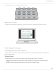
Shure Incorporated Model Variations MXWNCS8 Accepts eight boundary, bodypack, or handheld microphones or four gooseneck bases MXWNCS4 Accepts four boundary, bodypack, or handheld microphones or two gooseneck bases MXWNCS2 Accepts two boundary, bodypack, or handheld microphones. MXW8 Gooseneck bases are not supported on this charger ① Charging Slots (USB 3.0 Type A) Recharge and link microphones by connecting them to the USB slots on the charger.
Shure Incorporated Color Indicator Flashing Red Link procedure has been locked from the control software. Blue Charger is in High Efficiency Mode. ④ Microphone Link Button ◦ Press and hold for 6 seconds to link all microphones in the charger to channels of the associated Access Point Transceiver. ◦ Within the first minute of powering up the charger, press and release the Link button 3 times in succession to place the charger in High Efficiency Mode.
Shure Incorporated Different Connectors for the Same Channel Microphone Transmitters Description ① Power Button MXW6, MXW8: Press and hold the dedicated power button for three seconds to turn the transmitter on or off. MXW1, MXW2: Press and hold the Mute/Active button for five seconds to turn the transmitter on or off. ② Mute/Active Button Changes the audio status from Active to Mute, or Mute to Active. The button behavior for each transmitter type can be set independently from the Preferences tab.
Shure Incorporated ⑦ Handheld Cartridge MXW2 transmitter is compatible with the following cartridge types: SM58, Beta 58, SM86, VP68. ⑧ Gooseneck Microphone The gooseneck base is compatible with 5, 10, and 15” Microflex gooseneck microphones. ⑧ TQG Connector The MXW hybrid bodypack has a TQG connector for an external lavalier or headset microphone.
Shure Incorporated Hybrid Bodypack (MXW1) The bodypack secures to a belt or strap for hands-free, mobile communication. It features a TQG input for lavalier microphone connection and an integrated omnidirectional microphone. Wearing the Bodypack Transmitter • Clip the transmitter to a belt or pocket. • For best results, the belt should be pressed against the base of the clip.
Shure Incorporated Correct Microphone Placement • Hold the microphone within 12 inches from the sound source. For a warmer sound with increased bass presence, move the microphone closer. • Do not cover grille with hand. Boundary (MXW6/C, MXW6/O) The boundary transmitter sits on a table or desk to transmit speech while discreetly blending into any conference environment. Cardioid and omnidirectional versions are available.
Shure Incorporated Desktop Gooseneck Base (MXW8) The gooseneck base is compatible with 5, 10, and 15” Microflex gooseneck microphones.
Shure Incorporated MX405, MX410 & MX415 Bi-color Status Indicator MX405R, MX410R & MX415R Light Ring MX410DF, MX415DF Dualflex 23/97
Shure Incorporated Rechargeable Batteries MXW lithium-ion rechargeable batteries use advanced chemistry that maximizes transmitter runtime. Power management from the control software provides detailed visibility to critical battery parameters such as charge status, battery capacity, and cycle count. Batteries charge to 50% capacity in one hour and to full capacity in two hours using the MXW Networked Charging Station.
Shure Incorporated LED % Battery Charge 1 Flashing: <10% Solid: >10% 2 >25% 3 >50% 4 >75% 5 >95% Note: The LEDs do not illuminate in Energy Efficient Mode. NCS Power Modes The charging station can be operated in different power modes other than standard charging mode: Energy Efficient Mode Operate the charger in a low-energy mode to reduce power consumption. In this mode, only one LED indicator illuminates per channel after powering on. To change to Energy Efficient Mode: 1. 2. 3. 4. 5.
Shure Incorporated • After a power cycle of a charger in High Efficiency Mode, the charger visually indicates standard charging and any micro phones removed from the charger follow the configured Initial State from Charger preference in the APT configuration. • A microphone docked in a charger that is in High Efficiency Mode, which has not yet reached full charge, supports the legacy battery cycle count reset mechanism (hold mute button for 10 seconds to trigger cycle count reset).
Shure Incorporated Reset the Microphone Battery Statistics After installing a new battery, reset the battery health statistics that are stored in the microphone. 1. Place the transmitter with a new battery into a charging slot. You can use any powered MXW charging station. 2. Press and hold the mute button on the microphone until its LED flashes (~10 seconds). Caution: Securely hold the microphone while pressing the button to avoid damaging the USB ports on the charging station.
Shure Incorporated Tip: If additional runtime is needed, make sure the RF Power is at the lowest setting for the size of the room. RF power is set from MXW control software > Preferences tab. Battery Replacement Lithium Ion Batteries experience a linear reduction in capacity. Shure recommends establishing a battery replacement sched ule customized to the client requirements and replacing batteries when the capacity is no longer acceptable.
Shure Incorporated Connecting MXW Components MXW components are connected using Ethernet cables and a switch. For a small system with a single access point, the MXW Audio Network Interface functions as the switch. For systems with more than one access point, an additional gigabit switch is required for connecting all the components together. Requirements: • • • • Use shielded Cat 5e (or higher) Ethernet cables. Limit cable runs to ≤100 m between devices.
Shure Incorporated Multiple Group System (>1 Access Point) When an installation requires more than eight channels, additional MXW components can be connected to expand the system. A gigabit router is required to connect all components to the same network. The following are several topologies for multiple group systems. Use the Spectrum Scanner to ensure that there is sufficient RF availability for the installation. Large Single-Room Installation 1. Power on the DHCP-enabled router. 2.
Shure Incorporated Rack Installation Rackmount the device using the screws and washers supplied in the Hardware Kit. Follow these general best practices when installing equipment in a rack: • Ambient temperature of the rack should not exceed specified operating temperature range of the device. • Keep fan inlet and side air vents clear from obstructions and provide adequate space for airflow within the rack. • When possible, provide 1 RU of empty space between each device.
Shure Incorporated NCS Mounting Template Two-Channel Charger Wall Mount The two-channel charger includes a wall-mount to provide quick microphone access and storage in a classroom or conference room. NCS2 Secures to a Classroom Wall Tip: Paint the mount to match the wall for a less obtrusive installation. Installation 1. Determine the orientation and placement of the mount.
Shure Incorporated Placement Orientation Wall Drawer or tray 2. Leave room around the mount for cabling to the charging station. 3. Attach the mount to the wall. Use one set of screw holes depending on the orientation of the mount. Mount Screw Holes 4. Align the charger on the mount and secure with the screws.
Shure Incorporated Tip: Improve cable management using the cable tie holes on the mount.
Shure Incorporated Top View 35/97
Shure Incorporated Overall Dimensions Mount the Access Point Transceiver The directional antennas of the APT send and receive the RF signal in a cardioid pattern with the greatest sensitivity toward the face of the device. Always aim this side toward the microphone coverage area. Select a Location The access point is typically mounted to a ceiling or wall near the microphone coverage area.
Shure Incorporated Important: Always perform a "walk around" test to verify coverage before using a wireless system during a speech or perfor mance. Experiment with antenna placement to find the optimum location. If necessary, mark "trouble spots" and ask presenters or performers to avoid those areas. Cardioid RF Pattern Securing to a Wall or Ceiling Required Equipment • Two #8 screws at appropriate length* *Screw Length = Surface thickness + thread engagement (4.75 mm max.
Shure Incorporated External Cover for Painting The Access Point is supplied with an external cover that can be painted to match the decor of the installation. After it has been painted and dried, it snaps onto the front plate of the device. Power the Hardware ① Audio Network Interface (ANI) Connect the IEC power cable from the back panel to an AC power source. Turn on the power switch. ② Access Point Transceiver (APT) Connect a shielded Cat5e cable from the MXWAPT to network Port 1 of the MXWANI.
Shure Incorporated Fully Charge the Transmitters Whenever possible, charge to full the MXW transmitters before an event. Transmitters can be charged in any networked charg ing station, even if it is associated to another Group or on a separate network.
Shure Incorporated *Calculated with a new battery. Runtimes vary depending on battery health. Open the MXW Control Software Download and install the MXW control software to control the system from any computer on the MXW network. There are two different control interfaces for MXW devices: • MXW system: For comprehensive control of key setup, monitoring and management functions for the MXW system. Ac cessed from the Access Point Transceiver (APT).
Shure Incorporated System Set Up Group Devices to Form Audio Channels Use the group configuration to form the audio channel between the microphone, the access point (APT), charger and audio output device. The audio channel establishes the audio routing, RF coordination, and data control for a set of devices. Groups are comprised of networked devices (set to the same subnet). A component can belong to one group at a time.
Shure Incorporated 1. Go to the Configuration Tab 2. Select the Access Point Transceiver (APT) for Group 1 Assign the devices to groups from the Configuration tab of the MXW control software. Select an APT to determine group channel count (2, 4 or 8). Group 1 automatically uses the APT opened from the Devices list. Other networked (and open) APTs are available for additional groups. Select one or two Network Charging Station (NCS) to the access point. An additional charg er can be added to the group: 3.
Shure Incorporated Open Device A device that is not associated to a group is considered 'open.' Open devices are available for association by selecting the drop-down window in a Group row. The device will show Open in the Group column of the Utility page. Associated Device A device is considered 'associated' once it has been selected in a group row. Each device can only belong to one group at a time (and therefore one Configuration).
Shure Incorporated Channel Routing between Devices Channels are routed when charging stations and output devices are selected to fill the APT group (2-, 4-, or 8-channels). Once the devices are selected for the group, the channels are mapped between the charging slots, audio outputs and the wireless receiver. Group selections are made from the Configuration tab of the control interface.
Shure Incorporated Mixture of Gooseneck and Boundary Microphones When 4-channel and 8-channel chargers are selected, group channels five through eight are automatically routed to the back row of the 8-channel charger. 4-Channel Group Gooseneck Microphones This setup is used to fill a 4-channel group with gooseneck microphones. 2-Channel Group 2-Channel Charger The 2-channel charger supports boundary, handheld, and bodypack microphones.
Shure Incorporated Two 4-Channel Audio Network Interfaces Channels are routed across both interfaces to fill the group. 4-Channel Group 8-Channel Audio Network Interface Channels are routed to the first four outputs of the interface. Link Microphones to Group Channels Use the Networked Charging Station (NCS) to Link microphones to Access Point channels. Slots in the charger are mapped to the APT according to the Group setup from the Configuration tab.
Shure Incorporated Use the control software or the charging station to Link the microphones to APT channels. If desired, this feature can be disabled on the charging station so that Linking can only be per formed from the control software: 2. Link the microphones to channels. • Control Software: From the Configuration page, press the Link button for each charger in the Group. • Charging Station: Press and hold the Link button for 6 seconds.
Shure Incorporated Charged Backup Microphones Prepare for long events by linking fully-charged microphones as backups Shared Resources Easily add a temporary microphone without unlinking the most commonly used microphones. One Active Mic per Channel Only one microphone will operate on the channel at a time, blocking the second microphone from interfering with the RF and audio performance.
Shure Incorporated 2. Open the desired MXWAPT (double-click from the Devices view) and go to the Monitor tab. 3. Select Secondary in that channel's link slot. 4. Select the Link button on the channel strip to link that microphone. The charger LEDs will flash when the procedure is complete. Link multiple microphones: 1. 2. 3. 4. 5. Place the secondary microphones into the same charging slots that were used for the primary microphones.
Shure Incorporated *A comprehensive list of MXW command strings are available on the Shure website: www.shure.com, search "command strings". Large Installations Shure SystemOn Software For Managing Large Systems Shure SystemOn Audio Asset Management Software provides a central platform for managing mission critical, largescale de ployments of Shure audio hardware across corporate and higher education networks.
Shure Incorporated For specialized applications, such as multiple room installation, separate Configurations can be created to independently con trol component Groups. Primary Access Point When using a Configuration to manage multiple groups, the system dynamically assigns a Primary Access Point. All Access Points in that Configuration use the Primary Access Point as an entry point to the same control interface.
Shure Incorporated Density Mode Band Region Standard (SD) High (HD) Z14 Brazil 40 80 Z15 Taiwan 64 128 Scanning Available RF Spectrum The MXW Wireless components operate in unlicensed spectrum that is shared with other wireless devices operating in the same area, such as cordless phones, walkie-talkies and intercoms. The MXW control software features a scanning tool that surveys the RF spectrum for these devices.
Shure Incorporated Estimated Mic Channel Count The scanner provides two estimate levels for MXW microphones: Conservative (More Robust) Reference this channel estimate for maximum channel stability. It includes extra usable spectrum for optimal interference avoidance, allowing multiple microphones to find available frequencies simultaneously. Aggressive (More Channels). Reference this estimate to get the most channels on air.
Shure Incorporated JDECT regulations require an automatic cutoff in devices transmitting RF signals on the channels used by the PHS mobile phone network. When an MXW APT detects a signal above the -82dBm RSSI threshold, it stops transmitting and a warning displays on the Monitor tab of the MXW web application. Some applications may be outside of the range of the PHS mobile network and can benefit from use of the additional channels.
Shure Incorporated RF Coverage Optimal Placement of the Access Point Place the Access Point in the center of the installation for best coverage Using Multiple 2- or 4-Channel Access Points The MXW access point uses two sets of antennas to cover the operating spectrum. Each antenna set covers half of the times lots used for MXW channels. Eight-channel units use both antenna sets simultaneously; two- and four-channel units use one set at a time, operating on half of the available timeslots.
Shure Incorporated Alternate Antenna Modes to use the Full Spectrum Requirements The MXW system must be operating on a minimum firmware version of 8.0.3. Set Up 1. Open the desired MXWAPT by double-clicking from the Devices view. 2. Go to the Utility page. 3. Open the Device Properties window for the two- or four-channel access point (MXWAPT2 or MXWAPT4). 4. Note that the APT is set to Mode A by default (Device View > RF Mode Settings > RF Coordination Mode). Close out of the window. 5.
Shure Incorporated Networking Networking Best Practices Use the following best practices when setting up a network to ensure reliable communication: • Always use a "star" network topology by connecting each component directly to the switch or router. • Connect networked MXW gear to the same network and set to the same subnet. This ensures best system performance and maximum microphone count. • Use only 1 DHCP server per network. Disable DHCP addressing on additional servers.
Shure Incorporated 5. Repeat for any additional components. 6. To send updates to the devices, select Apply All to the Pending Changes field of the Utility page. Go to Utility > Device Properties to manage the interfaces of each MXW device on the network. Network Audio and Shure Control Data MXW devices transport two types of data over the network: Shure Control and Network Audio.
Shure Incorporated The two data types are configured differently for each MXW device. Go to Utility > Device Properties to view and edit the IP settings for MXW devices. Network Settings for Each MXW Device MXW Device Network Implementation for Audio and Control Access Point Transceiver (APT) Separate IP settings Audio Network Interface (ANI) Shared IP settings Networked Charging Sta tion (NCS) Shure Control settings only. (The NCS does not transport network audio.
Shure Incorporated Operating the Control Software over Wi-Fi When operating the MXW control software over WiFi, it’s important to set up the wireless router properly for best performance. The MXW System employs several standardbased protocols that rely on multicast. WiFi treats broadcast and multicast pack ets differently than general packets for backward compatibility reasons.
Shure Incorporated Latency Setting Maximum Number of Switches 1 ms 10 2 ms 10+ Connecting to an External Control System The MXW System connects to an AMX or Crestron control system via the Ethernet. Use only one controller per system to avoid messaging conflicts. For a comprehensive list of MXW command strings, visit: http://shure.custhelp.
Shure Incorporated Port TCP/UDP Protocol Description [4440, 4444, 4455]* udp Dante Dante audio routing 5353 udp mDNS† Used by Dante [8700-8706, 8800]* udp Dante Dante Control and Monitoring 8751 udp Dante Dante Controller 16000-65536 udp Dante Used by Dante *These ports must be open on the PC or control system to access the device through a firewall. †These protocols require multicast. Ensure multicast has been correctly configured for your network.
Shure Incorporated ① Devices List: Click a device to view its properties. Double click a device to open it. ② Search Bar: Search for a connected device by name. ③ Properties Pane: View identity, control, audio, and technical information for the selected device. ④ New Devices: Click "Initialize the devices" to set a passphrase for new devices. ⑤ Settings: Open the global Settings menu.
Shure Incorporated ① Language: Selects the language for the control software interface. This setting will be saved to the com puter. ② Network Setup: Select the network interface or refresh the list of available network interfaces. Using a Passphrase The software application must have an Admin passphrase created when a device is powered on for the first time, or after a fac tory reset. The passphrase may be changed from the Preferences tab in Admin view.
Shure Incorporated Monitor Tab ① Access Point Selection Determines which Access Point displays on the tab. ② Density Mode Selection Displays the density mode as selected in the APT device properties. ③ Spectrum Scanner Opens the Spectrum Scanner window. See Scanning Available RF Spectrum section for more details. ④ Global Mic Control Controls the status of all microphones in the configuration (all groups made from the Configuration tab).
Shure Incorporated View or change the microphone state: ◦ ◦ ◦ ◦ Active: On and passing audio to the network. Mute: On but the audio is muted. External: On and passing audio to an external controller that controls the mute/active behavior. Standby: On but in a 'sleep' state with audio muted. Standby conserves battery charge and enables a change to the microphone's status from the control software. ◦ Charging: Battery is charging. ◦ Inactive: Off or out-of-range.
Shure Incorporated ⑯ Bodypack Mic Options There are two input sources available on the MXW1 bodypack: the internal, omnidirectional microphone or the external, TQG input for lavalier or headset microphones. Select the input source preference: ◦ Auto: The internal mic is used until the MXW1 detects a connection at the TQG input. The microphone automatically se lects the external source whenever available. ◦ Internal: Audio source is always from the internal microphone.
Shure Incorporated Link Microphones Link all microphones in the charger to the access point audio channels. Up to two microphones can link to each audio channel, though only one is on air at-a-time. Use the secondary link slot to add a microphone for battery redundancy or flexibility during events. ① Link Slot Selection Up to two microphones link to each audio channel using the primary and secondary link slots.
Shure Incorporated ① Export Button Exports MXW device data to a text file (.csv). ② Device The device type or microphone channel.
Shure Incorporated These buttons apply or cancel any changes made to the device properties: ◦ Apply All: Confirms and executes all updates to device properties. At this time, the computer may lose connection to the control software. ◦ Cancel All: Clears all pending changes to the device properties. Device Properties Edit the settings for each device by opening the Device Properties window from the Utility tab.
Shure Incorporated Uses the device and channel name from the MXW web interface to overwrite the names in the Dante Controller (DC) soft ware by Audinate. Note: Use with caution, as this could break the routing configuration previously made in DC, causing audio interruptions. ⑤ Reboot The unit performs a power cycle. ⑥ Debug Mode For use by Shure Support personnel only. If selected, a power cycle is needed to resume normal operation.
Shure Incorporated Preferences Tab All preferences apply to each device in the Configuration. ① Switch Behavior Customize the switch on each transmitter type. ◦ ◦ ◦ ◦ Toggle (default): Press and release the button to change the status to Active or Mute. Push-to-talk: Hold button to pass audio. Push-to-mute: Hold button to mute the audio. Disabled: The button does not affect the audio.
Shure Incorporated Active Mute Solid Red Flashing Red Solid Red Off External LED Control *Not available for MX400R series gooseneck microphones ④ Mute Preference ◦ Local Mute - Individual (default): Each transmitter is muted individually. ◦ Local Mute - All: All transmitters mute when any transmitter is muted. ◦ External Mute: Transmitter audio is on, and muted from a 3rd-party controller. ⑤ RF Power Determines the RF coverage of an access point.
Shure Incorporated Guest: Monitoring only. ⑫ Save/Load Preferences Saves the preferences of the Configuration as a file to the computer. The file can be loaded and will overwrite the settings for all devices in the Configuration. Control Software for the MXW Audio Network Interface The MXW Audio Network Interface enables the control software to mange the analog inputs and outputs of the MXW system, in addition to the 4-port gigabit switch on the back panel of the network interface.
Shure Incorporated Channels Tab ① Channel Name Channel name is customizable by clicking in the text box. Names can be up to 12 characters long. ② Input Audio Meter Displays input audio levels prior to the analog-to-digital converter. ③ Mute Button Mutes or unmutes the channel's audio. The button illuminates red when a channel is muted. ④ Analog Input Level (A, B) Sets the analog input gain level: Line (default) or Aux.
Shure Incorporated Settings Pane ① General View or modify basic information about the selected device. ② Network Configure the network settings for your device. ③ Firmware Displays the current firmware version of the device. ④ Front Panel Lockout Disables the front panel controls on the hardware. Channels can still be selected for monitoring at the headphone jack. ⑤ Permissions The Administrator password is created when the interface is powered on for the first time, or after a factory reset.
Shure Incorporated General Settings ① Device Name Device names can be customized with up to 31 characters, except '=','.' or '@'. ② Device Model The device model number. ③ Serial Number The unique identifier used to register the device at the Shure website, guarantee the warranty, and troubleshooting with customer support. ④ Push to Dante Uses the device and channel name from the MXW web interface to overwrite the names in the Dante Controller (DC) soft ware by Audinate.
Shure Incorporated ②IP Settings View and edit the IP Address, Subnet Mask, and Gateway for each network interface. ③ MAC Address Unique identifier assigned to each network interface. ④ Audio Routing Mode ◦ MXW Mode: Enables automatic channel routing when the device is a part of an MXW group (assigned from the MXW Sys tem control software). ◦ Standalone Mode: Channels must be routed manually with Dante Controller software.
Shure Incorporated Dante Virtual Soundcard Dante Virtual Soundcard (DVS) acts as an audio driver used to monitor and record digital audio without additional equipment. DVS uses a computer's standard Ethernet ports to transmit and receive up to 64 channels from any Dante enabled device on the same network. Firmware Updates Firmware is embedded software in each component that controls functionality. Periodically, new versions of firmware are devel oped to incorporate additional features and enhancements.
Shure Incorporated Problem Indicator Solution Check that the output level of the ANI matches the input of the connecting equipment Verify APT is not performing a spectrum scan Audio is cut ting in an out (intermittent) Flashing Green Ensure all devices are on and have a stable network connection Use Dante Controller software (DC) to verify channel subscriptions Red Check master clock in DC (an MXWAPT must be master clock) Off Place the device in a Group to automatically route the audio Ensure the
Shure Incorporated Problem Indicator Solution Control Soft ware is per forming poor ly Indicators are moving slowly or not displaying in real time Reduce the number of windows or tabs that are open to the same Config uration See Network section for properly setting up the network Charger is not discovered by the Control Software The charger does not appear in the UI Ensure that the MXWNCS charger is not in High Efficiency Mode (solid blue Microphone Link LED) Additional Resources For additiona
Shure Incorporated From the Control Software 1. 2. 3. 4. 5. 6. Open the Utility Tab of the MXW control software. Select the Edit Properties button for the device. Select the factory reset check-box. Select Add Updates to save the setting to the edits queue. Repeat for any additional devices. Press the Apply All to make changes to all devices with edited properties.
Shure Incorporated MXW Device Description Part Number 4-Channel Audio Network Interface MXWNCS4 2-Channel Audio Network Interface MXWNCS2 Power Supply PS60 Bodypack Transmitter MXW bodypack transmitter (without lavalier microphone) MXW1/O Lavalier microphone See table Battery SB901A SM58 MXW2/SM58 SM86 MXW2/SM86 Beta58 MXW2/BETA58 VP68 MXW2/VP68 Battery SB902 Battery SB905* Omnidirectional MXW6/O Cardioid MXW6/C White omnidirectional MXW6W/O White cardioid MXW6W/C Batter
Shure Incorporated Lavalier Options Microphone Description Part Number ® Microflex 5mm Subminiature Lavalier, Omnidirectional, Black ® Microflex 5mm Subminiature Lavalier, Cardioid, Black MX150B/O-TQG MX150B/C-TQG ® Microflex Omnidirectional Subminiature Earset, Black MX153B/O-TQG ® Microflex Omnidirectional Subminiature Earset, Tan MX153T/O-TQG ® Microflex Omnidirectional Subminiature Earset, Cocoa MX153C/O-TQG ® Microflex 1cm Omnidirectional Lavalier, Black WL183 ® Microflex 1cm Superc
Shure Incorporated Microphone Description White with light ring indi cator Polar Pattern No cartridge included White dualflex with bicol or status indicator No cartridge included White dualflex with light ring indicator No cartridge included Length Part Number 5" (12.7 cm) MX405WRLP/N 10" (25.4 cm) MX410WRLP/N 15" (38.1 cm) MX415WRLP/N 10" (25.4 cm) MX410WLPDF/N 15" (38.1 cm) MX415WLPDF/N 10" (25.4 cm) MX410WRLPDF/N 15" (38.
Shure Incorporated Microflex Wireless Specifications System RF Carrier Frequency Range Band Region Frequency Range Z10 USA , Canada , Mexico 1920– 1930 MHz Z11 Europe , Asia , Middle-East 1880– 1900 MHz Z12 Japan 1893– 1906 MHz Z15 Taiwan 1880– 1895 MHz Z14 Brazil 1910– 1920 MHz Audio Frequency Response 65 Hz - 16 kHz Power Consumption 2.5 W Maximum Output Power 3.
Shure Incorporated Maximum Input Level Mic gain @ −16 dB −9 dBV Headphone Output 3.5 mm (1/8″), dual mono (will drive stereo phones) Maximum Headphone Output Power 1kHz @ 1% distortion, peak power, @16Ω 17.5 mW Antenna Type Internal, Spatial Diversity, Linear Polarization Antenna Gain Average -1.1 dBi Peak 0.5 dBi Charge Connector USB 3.
Shure Incorporated MXW2 Handheld Transmitter Microphone Capsule SM58, SM86, Beta58, VP68 Configuration Unbalanced Input Impedance @ 1 kHz >20 kΩ Battery Life SB902, Standard Density Mode SB902, High Density Mode SB905, Standard Den sity Mode SB905, High Density Mode Up to 15 hours Up to 16 hours Up to 23 hours Up to 29 hours Dimensions 226 mm x 51 mm (8.9 in. x 2.0 in.) L x Dia. Weight 369 g (13 oz.
Shure Incorporated Input Impedance @ 1 kHz >20 kΩ Gooseneck Options See accessories list Battery Life Standard Density Mode High Density Mode Up to 7 hours Up to 8 hours Dimensions 36 mm x 71 mm x 124 mm (1.4 in. x 2.8 in. x 4.9 in.) H x W x D Weight 193 g (6.8 oz.) Access Point Transceiver (APT) Network Interface RJ45: Gigabit Ethernet, Dante digital audio Plenum Rating UL 2043 Power Requirement Power over Ethernet (PoE) Class 0, 6.
Shure Incorporated Mounting Bracket 68 g (0.15 lbs) Networked Charging Station (NCS) Charge Time MXW1, MXW6, MXW8 50%=1 hour; 100%=2 hours; High Efficiency Mode=4-5 hours SB902 50%=1.5 hour; 100%=3 hours; High Efficiency Mode=4-5 hours SB905 50%=2.5 hour; 100%=5 hours; High Efficiency Mode=5-6 hours MXW2 Network Interface 10/100 Mbps Ethernet Power Requirement 15 V DC @ 3.
Shure Incorporated Line Aux Mic −84.5 dBV −95.2 dBV −106.5 dBV THD+N 20 Hz to 20 kHz +4dBu analog input, −10 dBFS digital input <0.05% Polarity Non-inverting, any input to any output Dimensions 44 mm x 483 mm x 366 mm (1.7 in. x 19.0 in. x 14.4 in.), H x W x D Weight MXWANI4 3.1 kg (6.9 lbs) MXWANI8 3.2 kg (7.
Shure Incorporated Digital Signal Processing AD/DA Converter 24-bit, 48 kHz Latency Estimated Nominal, ±0.1 ms Analog-to-Dante 0.21 ms Dante-to-Analog 0.
Shure Incorporated Maximum 17 50 Setting dBm mW Low -2 1 Medium 5 3 High 12 16 Maximum 19 80 MXW6, MXW8 Band: Z12 MXW1, MXW6, MXW8 Setting dBm mW Low 0 1 Medium 5 3 High 9 8 Maximum 12 16 MXW2 Setting dBm mW Low 0 1 Medium 7 5 High 9 8 Maximum 12 16 Wiring Diagram TA4M Connector 93/97
Shure Incorporated Audio Network Interface (ANI) Safety Information SAFETY PRECAUTIONS The possible results of incorrect use are marked by one of the two symbols—"WARNING" and "CAUTION"—depending on the imminence of the danger and the severity of the damage. WARNING: Ignoring these warnings may cause severe injury or death as a result of incorrect operation. CAUTION: Ignoring these cautions may cause moderate injury or property damage as a result of incor rect operation.
Shure Incorporated at 8 hours at 4 hours at 2 hours 110 dB SPL 115 dB SPL 120 dB SPL at ½ hour at 15 minutes Avoid or damage may occur at 1 hour WARNING • Battery packs may explode or release toxic materials. Risk of fire or burns. Do not open, crush, modify, disassemble, heat above 140°F (60°C), or incinerate. • Follow instructions from manufacturer • Only use Shure charger to recharge Shure rechargeable batteries • WARNING: Danger of explosion if battery incorrectly replaced.
Shure Incorporated can be determined by turning the equipment off and on, the user is encouraged to try to correct the interference by one or more of the following measures: • • • • Reorient or relocate the receiving antenna. Increase the separation between the equipment and the receiver. Connect the equipment to an outlet on a circuit different from that to which the receiver is connected. Consult the dealer or an experienced radio/TV technician for help. 1.
Shure Incorporated The CE Declaration of Conformity can be obtained from Shure Incorporated or any of its European representatives. For contact information please visit www.shure.com The CE Declaration of Conformity can be obtained from: www.shure.com/europe/compliance Authorized European representative: Shure Europe GmbH Headquarters Europe, Middle East & Africa Department: EMEA Approval Jakob-Dieffenbacher-Str. 12 75031 Eppingen, Germany Phone: +49-7262-92 49 0 Fax: +49-7262-92 49 11 4 Email: info@shure.