
User's Manual
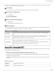
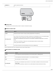
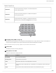
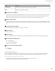
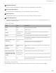
Table Of Contents
- Table of Contents
- MXW Microflex® Wireless
- IMPORTANT SAFETY INSTRUCTIONS
- Overview
- Overview
- Hardware Description
- Installation
- System Set Up
- System Set Up
- Large Installations
- Wireless Management
- Networking
- Networking
- Software
- Troubleshooting
- Accessories and Model Variations
- Microflex Wireless Specifications
- Microflex Wireless Specifications
- System
- Transmitters
- Gain Adjustment Range
- Maximum Input Level
- Headphone Output
- Maximum Headphone Output Power
- Antenna Type
- Antenna Gain
- Charge Connector
- Housing
- Recommended Storage Temperature Range
- MXW1 Hybrid Bodypack Transmitter
- Microphone Connector
- Input Impedance
- Internal Microphone
- Battery Life
- Dimensions
- Weight
- MXW2 Handheld Transmitter
- Microphone Capsule
- Configuration
- Input Impedance
- Battery Life
- Dimensions
- Weight
- MXW6 Boundary Transmitter
- Microphone Capsule
- Battery Life
- Dimensions
- Weight
- MXW8 Gooseneck-Base Transmitter
- Microphone Connector
- Configuration
- Input Impedance
- Gooseneck Options
- Battery Life
- Dimensions
- Weight
- Access Point Transceiver (APT)
- Networked Charging Station (NCS)
- Audio Network Interface (ANI)
- Audio Network Interface (ANI)
- Audio Frequency Response
- Dynamic Range
- Output Noise
- THD+N
- Polarity
- Dimensions
- Weight
- Housing
- Power Requirements
- Operating Temperature Range
- Storage Temperature Range
- Analog Connections
- Outputs
- Input(s)
- Headphone Output
- Digital Signal Processing
- AD/DA Converter
- Latency
- Networking
- Network Interface
- Uplink Port (Port 4)
- Power over Ethernet (PoE)
- Cable Requirements
- Network Addressing Capability
- Transmitter Output Power
- Wiring Diagram
- Safety Information
- Important Product Information
- Certifications

Shure Incorporated
11/97
◦
◦
◦
◦
◦
◦
Converts digital network audio to an analog output for each channel. When associated to an MXW group, access point
channels are automatically routed to the outputs of the ANI.
③ Channel Selector
Selects a channel to perform the following functions:
Action Function
Single Press
Listen to that channel at the headphone jack
Display and adjust the channel output level and attenuation
Monitor output signal on the level meter
Press and Hold (3 sec
onds)
Mute/unmute a channel. Mute is indicated by the mute LED.
④ Selected Channel LED
Illuminates when a channel is selected.
⑤ Signal Strength LED (sig/clip)
Indicates audio signal strength for each channel:
Green = Normal
Amber = Strong
Red = Clipping (to eliminate clipping, attenuate the signal level at the audio source)
⑥ Mute LED
Illuminates red when the channel output is muted (hold its channel select button for 3 seconds). A muted channel is still
routed to the HEADPHONE jack for monitoring or troubleshooting.
⑦ Input Level Selector
Set the selected channel to line- or aux-level to match the input signal.
⑧ Output Level Selector
Set the selected channel to an output level that matches the connecting device:
line: +4 dBu
aux: -10 dBV
mic: -30 dBV
⑨ Output Attenuation Control
Use the up/down buttons to attenuate the channel output from 0 dB (no attenuation) to -24 dB in 1 dB increments, and from
-24 to -78 in 3 dB increments.
⑩ Level Meter
Displaysaselectedchannel'saudiolevelindBFS.Itisgoodpracticetouse18dBFSontheoutputmeterasanapproxi
mation of 0 VU on an analog meter.
⑪ Hardware Status LEDs