
User's Manual
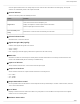
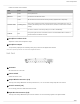
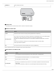
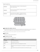
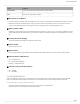
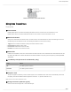
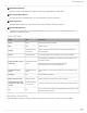
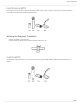
Table Of Contents
- Table of Contents
- MXW Microflex® Wireless
- IMPORTANT SAFETY INSTRUCTIONS
- Overview
- Overview
- Hardware Description
- Installation
- System Set Up
- System Set Up
- Large Installations
- Wireless Management
- Networking
- Networking
- Software
- Troubleshooting
- Accessories and Model Variations
- Microflex Wireless Specifications
- Microflex Wireless Specifications
- System
- Transmitters
- Gain Adjustment Range
- Maximum Input Level
- Headphone Output
- Maximum Headphone Output Power
- Antenna Type
- Antenna Gain
- Charge Connector
- Housing
- Recommended Storage Temperature Range
- MXW1 Hybrid Bodypack Transmitter
- Microphone Connector
- Input Impedance
- Internal Microphone
- Battery Life
- Dimensions
- Weight
- MXW2 Handheld Transmitter
- Microphone Capsule
- Configuration
- Input Impedance
- Battery Life
- Dimensions
- Weight
- MXW6 Boundary Transmitter
- Microphone Capsule
- Battery Life
- Dimensions
- Weight
- MXW8 Gooseneck-Base Transmitter
- Microphone Connector
- Configuration
- Input Impedance
- Gooseneck Options
- Battery Life
- Dimensions
- Weight
- Access Point Transceiver (APT)
- Networked Charging Station (NCS)
- Audio Network Interface (ANI)
- Audio Network Interface (ANI)
- Audio Frequency Response
- Dynamic Range
- Output Noise
- THD+N
- Polarity
- Dimensions
- Weight
- Housing
- Power Requirements
- Operating Temperature Range
- Storage Temperature Range
- Analog Connections
- Outputs
- Input(s)
- Headphone Output
- Digital Signal Processing
- AD/DA Converter
- Latency
- Networking
- Network Interface
- Uplink Port (Port 4)
- Power over Ethernet (PoE)
- Cable Requirements
- Network Addressing Capability
- Transmitter Output Power
- Wiring Diagram
- Safety Information
- Important Product Information
- Certifications

Shure Incorporated
12/97
Indicate the status of the hardware:
LED Color Status
Power Green Unit is powered on.
Ethernet Green Connected to an Ethernet device.
Network Audio
Green All connected receive channels are OK (receiving digital audio as expected).
Flashing Green
Oneormoreconnectedreceivechannelsexperiencingasubscriptionerrororisun
resolved (transmitting device is off, disconnected, renamed or has incorrect network
setting).
Off No receive channels connected (routing has not been established).
Lockout Red
Front panel gain and mute controls are locked. The LED will blink when a button is
pressed while the hardware is locked.
⑫ Headphone Volume Knob
Adjusts the volume to the headphone output.
⑬ Headphone Output
1/4" (6.35 mm) output jack for monitoring audio going to and from the digital audio network.
Note: Audio is present only when the unit is connected to a digital audio network.
Back Panel
① AC Power
IEC connector 100 - 240 V AC.
② Power Switch
Powers the unit on or off.
③ Output Block Connectors (1-8)
Three-pin, low-voltage differential connector provides a line-, aux- or mic-level analog output for each channel.
④ Chassis Ground (1-8)
Use to directly ground the cable shield to the chassis.
⑤ Input Block Connectors (A,B)
Three-pin, low-voltage differential input connector adds line- or aux-level analog signals to the digital network.