
User's Manual
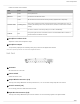
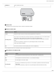
Table Of Contents
- Table of Contents
- MXW Microflex® Wireless
- IMPORTANT SAFETY INSTRUCTIONS
- Overview
- Overview
- Hardware Description
- Installation
- System Set Up
- System Set Up
- Large Installations
- Wireless Management
- Networking
- Networking
- Software
- Troubleshooting
- Accessories and Model Variations
- Microflex Wireless Specifications
- Microflex Wireless Specifications
- System
- Transmitters
- Gain Adjustment Range
- Maximum Input Level
- Headphone Output
- Maximum Headphone Output Power
- Antenna Type
- Antenna Gain
- Charge Connector
- Housing
- Recommended Storage Temperature Range
- MXW1 Hybrid Bodypack Transmitter
- Microphone Connector
- Input Impedance
- Internal Microphone
- Battery Life
- Dimensions
- Weight
- MXW2 Handheld Transmitter
- Microphone Capsule
- Configuration
- Input Impedance
- Battery Life
- Dimensions
- Weight
- MXW6 Boundary Transmitter
- Microphone Capsule
- Battery Life
- Dimensions
- Weight
- MXW8 Gooseneck-Base Transmitter
- Microphone Connector
- Configuration
- Input Impedance
- Gooseneck Options
- Battery Life
- Dimensions
- Weight
- Access Point Transceiver (APT)
- Networked Charging Station (NCS)
- Audio Network Interface (ANI)
- Audio Network Interface (ANI)
- Audio Frequency Response
- Dynamic Range
- Output Noise
- THD+N
- Polarity
- Dimensions
- Weight
- Housing
- Power Requirements
- Operating Temperature Range
- Storage Temperature Range
- Analog Connections
- Outputs
- Input(s)
- Headphone Output
- Digital Signal Processing
- AD/DA Converter
- Latency
- Networking
- Network Interface
- Uplink Port (Port 4)
- Power over Ethernet (PoE)
- Cable Requirements
- Network Addressing Capability
- Transmitter Output Power
- Wiring Diagram
- Safety Information
- Important Product Information
- Certifications

Shure Incorporated
13/97
◦
◦
◦
◦
◦
•
•
•
•
Note: This input is meant for balanced connection. If an unbalanced source is used, such as an IPOD or MP3 player, only use pins 1 (signal) and 3 (ground) of
the block connector. See Specifications sections for wiring diagrams.
⑥ Reset Button
Press and hold the button for five seconds to reboot the device with factory default settings.
⑦ Ethernet Status LED (Green)
Off = no network link
On = network link established
Flashing = network link active
⑧ Ethernet Link Speed LED (Amber)
Off = 10/100 Mbps
On = 1 Gbps (required for digital audio routing)
⑨ Network Interface
Four-port gigabit switch for connecting components together for a single MXW Group, or for connecting multiple devices to
a larger digital audio network. The following is a description of each port:
Port Description
Port 1 (PoE)
Provides Power over Ethernet (PoE) for the Shure access point and functions as a standard gigabit
port.
Ports 2 and 3
Standard gigabit ports enable the connection of another MXW network, additional MXWANIs, a
MXWNCS charging stations or an external control system.
Port 4 (Uplink)
Normal mode (default): this port functions the same as ports 2 and 3.
Uplink Mode: only transports control data. This mode blocks network audio and data for Shure Web
Discovery Application, Dante Controller and Dante Virtual Soundcard.
Access Point Transceiver (APT)
The access point transceiver is the hub of the audio signal flow and manages the RF stability of each microphone in the group.
The APT performs the following functions:
Receives and decrypts wireless audio signals from microphones in the group
Delivers the audio signal to the digital audio network and audio network interface (ANI)
Sendsandreceivescontrolinformation(suchasgainadjustmentandlinksettings)betweenthecomponents,MXWcon
trol software and 3rd party controllers.
Transmitsanencryptedaudiosignaltothemicrophone'sheadphoneoutputforlisteningtotranslatedaudioorotherexter
nal sources.
Model Variations
MXWAPT8 Eight-channel transceiver
MXWAPT4 Four-channel transceiver