
User's Manual
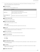
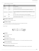
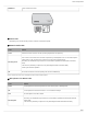
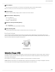
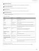
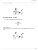
Table Of Contents
- Table of Contents
- MXW Microflex® Wireless
- IMPORTANT SAFETY INSTRUCTIONS
- Overview
- Overview
- Hardware Description
- Installation
- System Set Up
- System Set Up
- Large Installations
- Wireless Management
- Networking
- Networking
- Software
- Troubleshooting
- Accessories and Model Variations
- Microflex Wireless Specifications
- Microflex Wireless Specifications
- System
- Transmitters
- Gain Adjustment Range
- Maximum Input Level
- Headphone Output
- Maximum Headphone Output Power
- Antenna Type
- Antenna Gain
- Charge Connector
- Housing
- Recommended Storage Temperature Range
- MXW1 Hybrid Bodypack Transmitter
- Microphone Connector
- Input Impedance
- Internal Microphone
- Battery Life
- Dimensions
- Weight
- MXW2 Handheld Transmitter
- Microphone Capsule
- Configuration
- Input Impedance
- Battery Life
- Dimensions
- Weight
- MXW6 Boundary Transmitter
- Microphone Capsule
- Battery Life
- Dimensions
- Weight
- MXW8 Gooseneck-Base Transmitter
- Microphone Connector
- Configuration
- Input Impedance
- Gooseneck Options
- Battery Life
- Dimensions
- Weight
- Access Point Transceiver (APT)
- Networked Charging Station (NCS)
- Audio Network Interface (ANI)
- Audio Network Interface (ANI)
- Audio Frequency Response
- Dynamic Range
- Output Noise
- THD+N
- Polarity
- Dimensions
- Weight
- Housing
- Power Requirements
- Operating Temperature Range
- Storage Temperature Range
- Analog Connections
- Outputs
- Input(s)
- Headphone Output
- Digital Signal Processing
- AD/DA Converter
- Latency
- Networking
- Network Interface
- Uplink Port (Port 4)
- Power over Ethernet (PoE)
- Cable Requirements
- Network Addressing Capability
- Transmitter Output Power
- Wiring Diagram
- Safety Information
- Important Product Information
- Certifications

Shure Incorporated
15/97
◦
◦
◦
◦
◦
④ Reset Button
Press and hold the reset button for 10 seconds to reset the MXW system to factory default settings.
Note: The reset deletes group association and microphone links, and will reboot the device in DHCP mode.
⑤ Ethernet Port
Connect a shielded Cat5e (or higher) cable to a PoE source and the network.
⑥ Ethernet Status LED (Green)
Off = no network link
On = network link established
Flashing = network link active
⑦ Ethernet Link Speed LED (Amber)
Off = 10/100 Mbps
On = 1 Gbps (required for proper MXW functionality)
⑧ Cable Routing Path
Provides a path for the Ethernet cable to enable a flush-mount to the ceiling or wall.
Directional Antennas
Theaccesspointcontainsmultipledirectionalantennastoprovidesteady,reliablewirelesscommunicationwiththemicro
phones.ItsendsandreceivestheRFsignalinacardioidpatternwiththegreatestsensitivitytowardthefaceofthedevice.Al
ways aim this side toward the microphone coverage area.
Cardioid RF Pattern
Networked Charger (NCS)
The MXW networked charging station enables battery charging and channel linking from a single location. When a charger is
associated to a group, its channel slots are mapped to access point audio channels. Microphones can then be placed in the
slots to Link to these channels.
Any microphone can recharge in any NCS, regardless of Group association or network connection.
Caution: When the Link button on an associated charger is pressed, all microphones in the charger are mapped to channels
on an access point. This overrides any previously Linked microphones on those channels.