
User's Manual
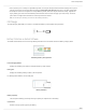
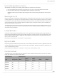
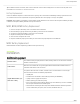
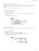
Table Of Contents
- Table of Contents
- MXW Microflex® Wireless
- IMPORTANT SAFETY INSTRUCTIONS
- Overview
- Overview
- Hardware Description
- Installation
- System Set Up
- System Set Up
- Large Installations
- Wireless Management
- Networking
- Networking
- Software
- Troubleshooting
- Accessories and Model Variations
- Microflex Wireless Specifications
- Microflex Wireless Specifications
- System
- Transmitters
- Gain Adjustment Range
- Maximum Input Level
- Headphone Output
- Maximum Headphone Output Power
- Antenna Type
- Antenna Gain
- Charge Connector
- Housing
- Recommended Storage Temperature Range
- MXW1 Hybrid Bodypack Transmitter
- Microphone Connector
- Input Impedance
- Internal Microphone
- Battery Life
- Dimensions
- Weight
- MXW2 Handheld Transmitter
- Microphone Capsule
- Configuration
- Input Impedance
- Battery Life
- Dimensions
- Weight
- MXW6 Boundary Transmitter
- Microphone Capsule
- Battery Life
- Dimensions
- Weight
- MXW8 Gooseneck-Base Transmitter
- Microphone Connector
- Configuration
- Input Impedance
- Gooseneck Options
- Battery Life
- Dimensions
- Weight
- Access Point Transceiver (APT)
- Networked Charging Station (NCS)
- Audio Network Interface (ANI)
- Audio Network Interface (ANI)
- Audio Frequency Response
- Dynamic Range
- Output Noise
- THD+N
- Polarity
- Dimensions
- Weight
- Housing
- Power Requirements
- Operating Temperature Range
- Storage Temperature Range
- Analog Connections
- Outputs
- Input(s)
- Headphone Output
- Digital Signal Processing
- AD/DA Converter
- Latency
- Networking
- Network Interface
- Uplink Port (Port 4)
- Power over Ethernet (PoE)
- Cable Requirements
- Network Addressing Capability
- Transmitter Output Power
- Wiring Diagram
- Safety Information
- Important Product Information
- Certifications

Shure Incorporated
30/97
1.
2.
3.
4.
5.
1.
2.
3.
4.
5.
6.
Multiple Group System (>1 Access Point)
When an installation requires more than eight channels, additional MXW components can be connected to expand the system.
A gigabit router is required to connect all components to the same network. The following are several topologies for multiple
group systems.
Use the Spectrum Scanner to ensure that there is sufficient RF availability for the installation.
Large Single-Room Installation
Power on the DHCP-enabled router.
Connect the router to a computer.
Connect each APT to a Power over Ethernet (PoE)-enabled port on the router. Use a PoE inserter if the router does not
provide it.
Connect each ANI to the router.
Connect chargers to the ANI ports, or to the router.
Local System Star Setup
Tominimizecabling,MXWcomponentscanusetheAudioNetworkInterfaceasalocalswitchthatconnectstoasharednet
work.
Power on the DHCP-enabled router.
Connect the router to a computer.
Connect the router to Port 2, 3, or 4 on the Audio Network Interface
Connect the Access Point Transceiver to the Port 1 of the Audio Network Interface.
Connect the Network Charging Station(s) to an open port(s) on the Audio Network Interface.
Repeat steps 2 - 4 for additional equipment.