
User's Manual

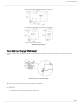

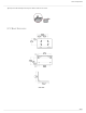


Table Of Contents
- Table of Contents
- MXW Microflex® Wireless
- IMPORTANT SAFETY INSTRUCTIONS
- Overview
- Overview
- Hardware Description
- Installation
- System Set Up
- System Set Up
- Large Installations
- Wireless Management
- Networking
- Networking
- Software
- Troubleshooting
- Accessories and Model Variations
- Microflex Wireless Specifications
- Microflex Wireless Specifications
- System
- Transmitters
- Gain Adjustment Range
- Maximum Input Level
- Headphone Output
- Maximum Headphone Output Power
- Antenna Type
- Antenna Gain
- Charge Connector
- Housing
- Recommended Storage Temperature Range
- MXW1 Hybrid Bodypack Transmitter
- Microphone Connector
- Input Impedance
- Internal Microphone
- Battery Life
- Dimensions
- Weight
- MXW2 Handheld Transmitter
- Microphone Capsule
- Configuration
- Input Impedance
- Battery Life
- Dimensions
- Weight
- MXW6 Boundary Transmitter
- Microphone Capsule
- Battery Life
- Dimensions
- Weight
- MXW8 Gooseneck-Base Transmitter
- Microphone Connector
- Configuration
- Input Impedance
- Gooseneck Options
- Battery Life
- Dimensions
- Weight
- Access Point Transceiver (APT)
- Networked Charging Station (NCS)
- Audio Network Interface (ANI)
- Audio Network Interface (ANI)
- Audio Frequency Response
- Dynamic Range
- Output Noise
- THD+N
- Polarity
- Dimensions
- Weight
- Housing
- Power Requirements
- Operating Temperature Range
- Storage Temperature Range
- Analog Connections
- Outputs
- Input(s)
- Headphone Output
- Digital Signal Processing
- AD/DA Converter
- Latency
- Networking
- Network Interface
- Uplink Port (Port 4)
- Power over Ethernet (PoE)
- Cable Requirements
- Network Addressing Capability
- Transmitter Output Power
- Wiring Diagram
- Safety Information
- Important Product Information
- Certifications

Shure Incorporated
31/97
•
•
•
•
•
•
Rack Installation
Rackmount the device using the screws and washers supplied in the Hardware Kit. Follow these general best practices when
installing equipment in a rack:
Ambient temperature of the rack should not exceed specified operating temperature range of the device.
Keep fan inlet and side air vents clear from obstructions and provide adequate space for airflow within the rack.
When possible, provide 1 RU of empty space between each device.
Securing the Charging Station
This kit provides washers and screws for securing a charging tray to a table or other surface. Use two kits for the NCS8.
Please refer to the NCS mounting template for screw hole placement.
Important: The top of the screw must extend exactly ⁹/₆₄ (0.149) inches (3.78 mm) above the surface (about 4½ threads).
Use the screws that best fit the thickness of the table.
Use a lock washer and flat washer for each screw.
If necessary, counterbore the screw head or add additional flat washers.
Required Thread Exposure
Use counterbore and washers as necessary depending on thickness of table