
User's Manual

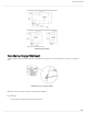

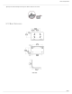


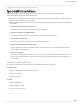
Table Of Contents
- Table of Contents
- MXW Microflex® Wireless
- IMPORTANT SAFETY INSTRUCTIONS
- Overview
- Overview
- Hardware Description
- Installation
- System Set Up
- System Set Up
- Large Installations
- Wireless Management
- Networking
- Networking
- Software
- Troubleshooting
- Accessories and Model Variations
- Microflex Wireless Specifications
- Microflex Wireless Specifications
- System
- Transmitters
- Gain Adjustment Range
- Maximum Input Level
- Headphone Output
- Maximum Headphone Output Power
- Antenna Type
- Antenna Gain
- Charge Connector
- Housing
- Recommended Storage Temperature Range
- MXW1 Hybrid Bodypack Transmitter
- Microphone Connector
- Input Impedance
- Internal Microphone
- Battery Life
- Dimensions
- Weight
- MXW2 Handheld Transmitter
- Microphone Capsule
- Configuration
- Input Impedance
- Battery Life
- Dimensions
- Weight
- MXW6 Boundary Transmitter
- Microphone Capsule
- Battery Life
- Dimensions
- Weight
- MXW8 Gooseneck-Base Transmitter
- Microphone Connector
- Configuration
- Input Impedance
- Gooseneck Options
- Battery Life
- Dimensions
- Weight
- Access Point Transceiver (APT)
- Networked Charging Station (NCS)
- Audio Network Interface (ANI)
- Audio Network Interface (ANI)
- Audio Frequency Response
- Dynamic Range
- Output Noise
- THD+N
- Polarity
- Dimensions
- Weight
- Housing
- Power Requirements
- Operating Temperature Range
- Storage Temperature Range
- Analog Connections
- Outputs
- Input(s)
- Headphone Output
- Digital Signal Processing
- AD/DA Converter
- Latency
- Networking
- Network Interface
- Uplink Port (Port 4)
- Power over Ethernet (PoE)
- Cable Requirements
- Network Addressing Capability
- Transmitter Output Power
- Wiring Diagram
- Safety Information
- Important Product Information
- Certifications

Shure Incorporated
36/97
•
•
•
•
•
Overall Dimensions
Mount the Access Point Transceiver
The directional antennas of the APT send and receive the RF signal in a cardioid pattern with the greatest sensitivity toward the
face of the device. Always aim this side toward the microphone coverage area.
Select a Location
Theaccesspointistypicallymountedtoaceilingorwallnearthemicrophonecoveragearea.Forbestresults,performaSpec
trum Scan at potential locations to find the optimal placement (see Wireless Management section for more details).
Use the following best-practices when selecting a location for the device:
Direct the face of the access point toward the intended coverage area.
Position the access point so there is nothing obstructing a line of sight to the microphones.
Keep device away from large metal objects.
Keep at least eight feet between access points.
Mount with its reset button accessible, as it may be useful for troubleshooting.