
User's Manual


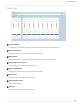


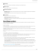
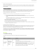
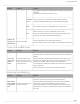
Table Of Contents
- Table of Contents
- MXW Microflex® Wireless
- IMPORTANT SAFETY INSTRUCTIONS
- Overview
- Overview
- Hardware Description
- Installation
- System Set Up
- System Set Up
- Large Installations
- Wireless Management
- Networking
- Networking
- Software
- Troubleshooting
- Accessories and Model Variations
- Microflex Wireless Specifications
- Microflex Wireless Specifications
- System
- Transmitters
- Gain Adjustment Range
- Maximum Input Level
- Headphone Output
- Maximum Headphone Output Power
- Antenna Type
- Antenna Gain
- Charge Connector
- Housing
- Recommended Storage Temperature Range
- MXW1 Hybrid Bodypack Transmitter
- Microphone Connector
- Input Impedance
- Internal Microphone
- Battery Life
- Dimensions
- Weight
- MXW2 Handheld Transmitter
- Microphone Capsule
- Configuration
- Input Impedance
- Battery Life
- Dimensions
- Weight
- MXW6 Boundary Transmitter
- Microphone Capsule
- Battery Life
- Dimensions
- Weight
- MXW8 Gooseneck-Base Transmitter
- Microphone Connector
- Configuration
- Input Impedance
- Gooseneck Options
- Battery Life
- Dimensions
- Weight
- Access Point Transceiver (APT)
- Networked Charging Station (NCS)
- Audio Network Interface (ANI)
- Audio Network Interface (ANI)
- Audio Frequency Response
- Dynamic Range
- Output Noise
- THD+N
- Polarity
- Dimensions
- Weight
- Housing
- Power Requirements
- Operating Temperature Range
- Storage Temperature Range
- Analog Connections
- Outputs
- Input(s)
- Headphone Output
- Digital Signal Processing
- AD/DA Converter
- Latency
- Networking
- Network Interface
- Uplink Port (Port 4)
- Power over Ethernet (PoE)
- Cable Requirements
- Network Addressing Capability
- Transmitter Output Power
- Wiring Diagram
- Safety Information
- Important Product Information
- Certifications

Shure Incorporated
72/97
◦
◦
◦
◦
◦
◦
◦
◦
Preferences Tab
All preferences apply to each device in the Configuration.
① Switch Behavior
Customize the switch on each transmitter type.
Toggle (default): Press and release the button to change the status to Active or Mute.
Push-to-talk: Hold button to pass audio.
Push-to-mute: Hold button to mute the audio.
Disabled: The button does not affect the audio.
② Initial State from Charger
Assigns the state for the transmitter after it has been removed from the charger:
Active: On and passing audio to the network.
Mute: On but the audio is muted.
Standby: On but in a 'sleep' state with audio muted. Standby conserves battery charge and enables a change to the
transmitter's status from the control software.
Off: Power is off. A transmitter in this state cannot be remotely controlled by the software.
Note: These settings only apply to standard mode; transmitters in high efficiency mode are always powered off when removed from the changer.
③ Active/Mute LED Behavior
Set the behavior of the mute/active LED for each transmitter type. Standby mode is always represented with a pulsing red
LED.
Active Mute
Solid Green* Solid Red