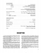
VA302 SERIES @hfd(>M&fih OPERATING AND SERVICE MANUAL Manufactured by SHURE BROTHERS INC. 222 Hartrey Avenue Evanston, Illinois 60204 U.S.A. Copyright 1978, Shure Brothers Inc. AL406 (RE) 27A818 Printed in U.S.A.
VA302 Series Vocal Master SPECIFICATIONS VA302 Series Console Amplifier Type . . . . . . . . . . . . . . . . . . . . . . . . . . . . . . . . . . ..All silicon transistor mixer/power amplifier Power Output . . . . . . . . . . ..I00 watts continuous '(RMs); (to 8 ohm load, see Figure 3, Page 7) Voltage Gain . . . . . . . . . . . . . . . . . . . . . . . . . . . . . . . . . . . . . .80db Input Attenuator "Out" (8 ohm load) 65 db lnput Attenuator "In" (8 ohm load) . 2 db 40 Hz. to 20,000Hz.
Console (Continued) power Supply: VA302-C . . . . . . . . . . . . . . . . . . . . . . . . . . . . . . . . . . . . . . . . . . . . . . . . . . ,120 volts, 60 HZ. VA302E-C . . . . . . . . . . . . . . . . . . . . . . . . . . . . . . . . . . . . . . . . . .120/240 . volts, 50160 HZ. Factory wired for 240 volt operation. VA302E6-C . . . . . . . . . . . . . . . . . . . . . . . . .,100, 120,140, 200, 220, 240 volts, 50160 Hz. Switch selectable. Power Consumption . . . . . . . . . . . . . . . . . . . . . . . . . .
FIGURE 1. 6, Individual Channel "Treble & Bass" Controls Front Panel Controls (Refer to Figure 1) 1. "Anti Feedback" Switches (Four). 2. "Reverb Intensity" Control. 3. "Reverb Treble & Bass" Controls (Dual Concentric). 4. "Master Reverb" Switch. 5. Individual Channel "Volume" Controls (Six). 7. 8. 9. 10. 11. (Six, Dual Concentric). Individual Channel "Reverb" Switches (Six). "Master Volume" Control. "On-Off-On" Power Switch. V.U. Meter "Hi/Lo" Sensitivity Switch. V.U. Meter. 1 I FIGURE 2.
General Operating Instructions: 1. Set all front panel controls in the following manner: All switches (I), (4), (7), set to "Out" position; "Reverb Intensity" Control (2), and all "Volume" Controls (5) and (8), set at "0"; all "Treble" and "Bass" Controls (3) and (6), set in the "flat response" position (indicator ribs at 12:OO o'clock); "On-Off-On" Switch (9) set in the "Off" position; "Hi-Lo" Sensitivity Switch (10) in the "Hi" position. 2. Unwrap the A.C.
lnput Connections: Six individugl input connectors are provided on the rear panel of the Console. These connectors are professional 3-pin female audio connectors (25). The Console is designed to operate with any high quality dynamic or ribbontype low impedance microphone. The main advantage of low impedance microphones is that virtually unlimited cable lengths may be used, whereas high impedance microphones require that cable length not exceed 6m (20 ft).
The following list shows various speaker combinations and the resultant impedance loads which are suitable for use with the Vocal Master Console: QUANTITY and SPEAKER MODEL IMPEDANCE OHMS (NOMINAL) 5 ~ ~ 3-S0 1 6 VA301 -S 1 VA300-S and 1 VA301-S 1 VA300-S and 2 VA301-S 1 VA3OO-S and 3 VA301 -S 1 VA300-S and 4 VA301 -S 2 VA3OO-S and 1 VA301-S 2 VA3OO-S and 2 VA301-S If additional speakers (more than in the table above) are required, use a Shure Power Master Amplifier to drive the extra speakers.
VA302 Power Requirements: The ~ ~ 3 0 2 Vocal - 6 Master is furnished with a three conductor power cable and three-prong plug. Connect the power cable to an outlet which supplies 120 10% volts A.C., 60 Hz power. The three-position toggle switch on the front panel controls power to the amplifier. This switch (9) is also used to reverse line polarity for minimum hum. If extension cords are required to supply power to the VA302, a high quality #18 gauge or larger cord should be used.
If feedback occurs, locate the one Anti Feedback switch (1) which eliminates the feedback. Gain may then be increased or tone control increased until another feedback pitch is apparent. One of the other filters may then be introduced which will eliminate that feedback. IMPORTANT: no more than two filters should be used simultaneously; the effect of more than two filters is one of reducing overall gain and the overall tonal quality of the system may be significantly affected.
It should be noted that operation of the Console with the meter reading into the red portion of the scale does not indicate any type of overload. "Pinning" the meter, while not a good practice, will not damage it. If the Console is operated without a speaker load (nothing plugged into the "Speaker" jacks) the VU meter readings are meaningless because the Console is delivering zero power. Just disregard the meter readings if the Console is operated in this manner.
resistance pad (attenuator) will be required in the line from the Console to the echo device input. If the echo device input is suitable for only high impedance microphones a resistive pad consisting of a 100 kilohm and a 3.3 kilohm resistor is required. (See figure 5.) Almost all makes of echo units use different output levels; these may generally be compensated for by use of the gain controls on the echo unit and the "Echo Gain" control on the Console.
Adjust the Echo Gain control and the mixer volume controls to matcti the gain of the Console inputs. With the mixer connected in this configuration the individual Reverb In-Out switches on the Console should be set to the "In" position. When these switches are set to the "Out" position, that individual channel will be muted, or "cued." See the description on "cuing." Still more inputs may be added by stacking additional mixers onto the first mixer. See the Mixer Operation Instructions.
Set the controls on the second Console as follows: Anti Feedback'Switches to "Out," Master Reverb Switch "Out," Individual Volume Controls to "0," and the Master Volume to "5." Adjust the Echo "Gain" Control to approximately 113 rotation from the C.C.W. off position, and use this control as a volume control to obtain the same amplification level from both of the Consoles. Once the Echo "Gain" Control is preset, the output of the second Console will "follow" all control settings of the original Console.
INDIVIDUAL REVERB SWITCH IN WPUT , 1 5 0 8 ATTEN BASS& -TREBLE CONT'L -:-I JACK SWITCH OPERATES WHEN PLUG IS INSERTED IND - VOLUME coNTL OUT ATTENLATOR CJ'yLITCH r , MASTER I REVERB BASS a TREBLE CONTROLS - REVERB SPRING -. INTENSITY CONTROL 0i ~'. REVERB I vU METER AUX HIGH L E V E L OUTPUT 'TO SPEAKERS MIC L E V E L OUTPUT (HIGH/ L O W 2 ) VA302-C SERIES FUNCTIONAL DIAGRAM FIGURE 11.
FIGURE 12. Driver Transistors: The driver transistors Q33 and Q34, Figure 12, Page 15, are located on the amplifier chassis. Before removing these transistors, write down the lead color and location at each transistor solder junction. If replacing transistors, apply type 120 Wakefield thermal joint compound to each side of the insulation wafer to provide good thermal transfer from transistor to chassis.
FIGURE 13. FIGURE 14. Small Signal and Predriver Transistors: Transistors Q1 through Q30, Figure 14, Page 16, and Q31 and (232, Figure 12, Page 15, are mechanically supported by their leads. When replacing these transistors, it is imperative that proper lead configuration be followed. A minimum of soldering heat should be used to avoid damage to the transistor. Refer to the lower right corner of the circuit diagram, Figure 17, Page 21, for lead code.
If all conditions in the following table are met, the transistor may,be considered free of any gross defect; if any of the following conditions are not met, the transistor should be replaced. See lower right corner of circuit diagram, Figure 17, Page 21, for transistor terminal code. OHMMETER CONNECTIONS "Plus" "Minus" Lead Lead Collector Emitter Collector Emitter Base Base Emitter Collector Base Base Collector Emitter OHMMETER READING N.P.N. P. N.P.
VA300-S Speaker Servicing: 1. Unplug cables from speaker jacks. 2. Using an ohmmeter, measure the resistance of the speaker column. The resistance should be between 12 and 16 ohms. Readings outside of these limits indicate possible failure. 3. Remove back of cabinet. 4. Disconnect one end of the lead connected between the two 10 inch loudspeakers. 5. Using an ohmmeter, measure resistance of the voicecoil of each loudspeaker individually. Each 10 inch speaker should measure between 12 and 16 ohms.
I ITP. I .. REPL. KIT NO. REPLACEMENT PARTS LIST FOR VA302-C SERIES CONSOLES QTY. 1 PART NO. I COMMERCIAL ALTERNATE DESCRIPTION Capacitor, 2500 x 100 Capacitor, 4000 x 60 Silicon Rectifier, 3A., 200 V. Zener Diode, 22V,, 1 W., 5% Silicon Rectifier, 100 V., %A. Zener Diode, 3.6 V., 1 W., 5% Germanium Diode Silicon Diode, 50 V., '/PA. A.C. Fuse (VA302 and VA302E) A.C. Fuse (VA302E6 only) for 200-240 volts A.C. Fuse (VA302E6 only) for 100-140 volts D.C. Fuse (VA302 and VA302E) D.C.
Notes to Circuit Diagram D.C. Voltage Measurements: Check the DC voltages first, because any deviation from the nominal voltages will affect the AC voltage. In the power amplifier, Q31 to Q38, the key DC voltages are 9 4 (collector of Q33, 035, and Q37), -22 (collector of Q31), and the split voltage at the junction of R17, R19, R20, and R22. If these three key DC voltages are correct, then proceed with the AC voltage measurements. The numbers within the symbols o on the circuit diagram denote the D.C.
I VA302-C CIRCUIT DIAGRAM FIGURE 17.
Eil(ii VA302E-C POWER SUPPLY CIRCUIT DIAGRAM 120 VOLT POWER SUPPLY WIRING THERMAL OVERLOAD GRWBLK. BLACK RED T I BLUE 600 RED/BLK. 2 4 0 VOLT POWER SUPPLY WIRING YEL./BLK. I I GRN./BLK. RED SI FIGURE 18. VA302E6-C POWER SUPPLY CIRCUIT DIAGRAM 2 0 0 - 2 4 0 VOLT 1.6 AT 100- 140 VOL TI 2 4 0 V. POSITION CHASSIS POWER SI 5 7' 4 I 100 V. POSITION '2 4 I 4 I 1 4 0 V. POSITION 1 2 0 V. POSITION VOLTAGE 4 I 2 0 0 V. POSITION 4 I 2 2 0 V.