
Service manual


It should be noted that operation of the Console with
the meter reading into the red portion of the scale does not
indicate any type of overload. "Pinning" the meter, while
not a good practice, will not damage it. If the Console is
operated without a speaker load (nothing plugged into the
"Speaker" jacks) the VU meter readings are meaningless
because the Console is delivering zero power. Just disre-
gard the meter readings if the Console is operated in this
manner.
Auxiliary Hi-Level Output:
A phone jack on the rear panel marked "Aux. Hi-Level
Output" is provided for connections to tape recorders for
making recordings, or to additional power amplifiers, such
as the Shure Power Master
PM300 Series. For specific in-
structions for such connections, see the section marked
Special Operating Instructions.
The signal at this jack is the same signal that drives the
console power amplifier and is considered to be an auxil-
iary, high impedance output for driving high-level,
high-
impedance inputs. Note that all the Console controls, Mas-
ter Volume, Anti Feedback, Reverb, etc., affect this signal.
The interconnecting cable used with this jack should be
a low capacitance, single conductor, shielded cable (such
as Belden
#8401, #8410, #a41 1).
Limit the cable length to 15m (50 ft) to avoid loss of high
frequency signal and to reduce the possibility of hum
pickup.
Microphone Level Output:
A microphone level output connector is provided on the
rear panel of the Console. This connector is a professional
three-pin male audio connector (20). A "Lo Z-Hi Z" im-
pedance selector switch (19) is located above the output
connector. This screwdriver-slot, slide switch selects the
impedance of the microphone output. The signal at this
connector is the same signal (but at
mic, level) that drives
the Console power amplifier and is designed to work into an
amplifier or tape recorder microphone input. This output
is useful for providing a signal feed to a house P.A. system
for coverage in other rooms, or for low level fill in difficult
coverage areas of irregularly shaped rooms.
With the "Lo Z-Hi Z" switch in the "Lo
Z"
position the
microphone output connector is switched to a balanced
low impedance transformer; connector Pins
2
and
3
are
"hot" and Pin
1
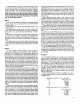
is "ground." With the switch in the "Hi Z''
position the connector is sditched to provide a high impe-
dance output; connector Pin
3
is "hot" and Pin 1 is
"ground." See figure
4.
.
-
SHIELD-
,-
_-__--L
MIC. OUTPUT MIC. OUTPUT
HIGH IMPEDANCE
LOW
IMPEDANCE
(BALANCED LINE)
MICROPHONE OUTPUT
PLUG
CONNECTIONS
FIGURE
4.
Microphone
Output Plug
Connections.
If the low impedance output is to be used with an un-
balanced input, such as an input that uses a phone plug
or other connector with only two connections, connect Pins
1 and 2 of the Console microphone output connector to-
gether. Use this as the "ground" and connect Pin 3 as the
"hot."
It should be noted that the signal at this connector is
"out-of-phase" with the Microphone Inputs. See page
6,
lnput Connections, for information on phasing.
VA302
Series
Vocal
Master
Echo:
Echo may be introduced into the Console by using an
accessory echo device (such as an Echolette or Dynacord).
To use an external echo device in conjunction with the
Console, interconnect the two units as follows: attach low
capacitance, single conductor, shielded cable to the Con-
sole jack marked Echo "To Input." Connect the opposite
end of this cable to the echo device jack marked "Input"
(Aux. High Level). Connect a similar cable to the echo de-
vice jack marked "Output" (Aux. High Level) and connect
the opposite end of this cable to the Console jack marked
Echo "To Output."
Using the "Echo Gain" Control in conjunction with the
level controls on the echo
u.nit, the echo signal may be
balanced with the gain of the Console so there is no change
in level when the individual Reverb In-Out switches are
operated.
When connected in the manner described, the individual
channel Reverb In-Out switches will offer selective echo in
addition to selective internal reverb. With the Master Re-
verb In-Out switch in the "Out" position, the individual
TO CONSOLE
ECHQ "TO
IN-
TO ECHO DEVICE
PUT' JACK HIGH IMPEDANCE
MICROPHONE
INPUT JACK
-
RESISTORS ARE 112 WATT
10%
CARBON
FIGURE
5.
channel Reverb switches will select "dry" (no echo) in the
"In" position and "Echo" in the "Out" position.
Changing the Master Reverb In-Out switch to the
"In"
position will permit selection of echo (individual channel
Reverb switch "Out") or reverb (individual channel Reverb
switch
"In").
The output signal of the Console at the jack marked
Echo "To Output" is considered high level and is suitable
for use with loads of 10 kilohms or greater. The jack marked
Echo "To Input" presents a 40 kilohm load to the source
and will accept high level signals. Some echo units employ
inputs suitable only for very low level; in such cases, a