0RGHO 6&0 6&0 ( 8VHU *XLGH 6&0 6&0 ( (,*+7 &+$11(/ 0,&523+21( 0,;(5 ¢ 6KXUH ,QFRUSRUDWHG & 5HY 3ULQWHG LQ 8 6 $
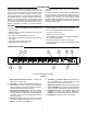
DESCRIPTION switchable 48 V phantom power, and a 1/4-inch send/receive insert jack. The SCM800 operates on 120 Vac power; the SCM800E operates 230 Vac power. Both models are supplied with rackmounting hardware, link cable and removable block terminal connectors. An accessory rack panel adapter (Model RKC800, available separately) converts the removable block input and output connectors to XLR connectors, and the Aux connectors to phono jacks.
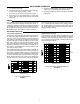
SCM800 REAR PANEL 120VAC 50/60 Hz 200mA LINK OUT AUX/INS/INS INSERT INSERT INSERT INSERT INSERT INSERT INSERT INSERT (SWITCH) AUX IN MIC/PHM/LINE MIC/PHM/LINE MIC/PHM/LINE MIC/PHM/LINE MIC/PHM/LINE MIC/PHM/LINE MIC/PHM/LINE MIC/PHM/LINE LINE SWITCH SWITCH SWITCH SWITCH SWITCH SWITCH SWITCH SWITCH OUTPUT LINK IN +Ć 11 12 13 8 14 +Ć 7 6 +Ć 16 17 +Ć 5 +Ć 15 4 3 +Ć 18 +Ć 2 +Ć MICĆ LEVEL (MIC) 1 +Ć PHANTOM LINEĆ (PHM) LEVEL (LINE) (SWITCH BEHIND CONNECTOR) MODEL SCM800/E REAR PAN
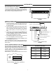
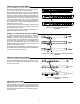
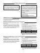
SYSTEM SETUP RACK MOUNTING THE SCM800/E To mount an SCM800 or SCM800E in a standard 483 mm (19-inch) audio equipment rack so that the front panel faces out, as shown in Figure 4. Then secure secure the mixer to the rack with the four supplied Phillips head screws. RACK MOUNTING THE SCM800/E FIGURE 4 SCM800/E CONNECTIONS Refer to Figure 5 and proceed as follows: 1. Connect microphone- or line-level signal sources to the Channel Input connectors (use conventional two-conductor shielded cables). 2.
LINKING MULTIPLE SCM800 MIXERS Up to four SCM800 mixers can be “linked” using the supplied link cables If additional inputs are needed. Such a configuration can provide 32 mic inputs. Refer to Figure 6. When multiple SCM800 mixers are linked, all input signals appear at all linked mixer outputs––there is no master-slave relationship. The output controls and functions of each linked mixer are post-link and do not affect the signals appearing at other linked mixer outputs.
BASIC MIXER OPERATION 1. Turn on the Power switch. 2. Adjust each channel level so that its Overload LED flickers only during very loud speech or noise. 3. Turn unused channel controls full counterclockwise. 4. Adjust the Low-Cut and High-Frequency controls adjacent to each Input Gain control until all microphones sound alike. 5. Adjust the SCM800 Master level control for the desired output level, as indicated by the output peak meter. 6. Adjust the headphones volume level with the PHONES control knob.
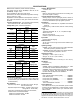
SPECIFICATIONS Measurement Conditions (unless otherwise specified): Line voltage 120 Vac, 60 Hz (SCM800) or 230 Vac, 50 Hz (SCM800E); full gain; 1 kHz. Source impedances: Mic 150 :, Line 150 : Terminations: Line 10 k:, Phones 300 : tip-sleeve and ringsleeve), Direct Out 10 k: Equalization controls adjusted for flat response, Channel 1 gain control full clockwise, other gain controls full counterclockwise Common Mode Rejection >70 dB at 1 kHz Frequency Response (Ref .
INTERNAL MODIFICATIONS WARNING: All modifications must be performed by qualified service technicians. Voltages in this equipment are hazardous to life. No user-serviceable parts inside. Refer all servicing to qualified service personnel. The safety certifications of the SCM800 do not apply when the operating voltage is changed from the factory setting. ABOUT PRINTED CIRCUIT BOARD MODIFICATIONS S A jumper is represented by “X” on the printed circuit board legend, a resistor is represented by an “R.
INSERTING A 15 dB MICROPHONE PREAMPLIFIER PAD Each channel’s microphone preamplifier gain can be reduced by 15 dB. This may be desirable with extremely high-output microphones. Procedure: To pad the gain of the MIC position 1. Remove surface mount resistor R1023. 2. Solder a 680 : resistor at jumper X112. For a greater gain reduction, use a resistor with a value greater than 680 :. Use a lesser value resistor for less reduction. To pad the gain of the PHM (phantom) position: 1.
REMOTE VOLUME CONTROL OF CHANNELS The channel, aux, or master levels can be controlled remotely by a dc voltage via an external VCA (Voltage Controlled Amplifier). An example of an external VCA is the ST-VCA1 from Radio Design Labs (1–800–281–2683 or www.rdlnet.com). Procedure: For channel control: 1. Connect the tip of a 1/4-in. connector to the line input of the VCA, and the sleeve to the ground of the VCA. 2. Connect the ring to the line output of the VCA. 3. Plug the 1/4-in.
SHURE Incorporated http://www.shure.com United States, Canada, Latin America, Caribbean: 5800 W. Touhy Avenue, Niles, IL 60714-4608, U.S.A. Phone: 847-600-2000 U.S.