SRlOl Series 2 Audio Console OPERATION AND SERVICE MANUAL Manufactured by SHURE BROTHERS INC. 222 Hartrey Avenue Evanston, Illinois 60204 U.S.A. Copyright 1979, Shure Brothers Inc. 27A1171 (SD) (95E652) Printed in U.S.A.
SR101 Series 2 Audio Console SPECIFICATIONS Equipment Type . . . . . All silicon transistor mixerlpreamplifier Number of lnput Channels . . . . . . 8 Power Output . . . . . . . . . +19 dBm (program line level) Voltage Gain* Program . . . . .73 k 3 dB MIC input to LlNE LEVEL out 50 k 3 dB AUX input to LlNE LEVEL out 23 t 3 d ~MIC input to MIC LEVEL out Monitor . . . . . . . . . .
SR101 Series 2 Audio Console SPECIFICATIONS Feedback Filter Frequencies . . . . . . . . I 3 0 Hz; 800 Hz; 2 kHz; 5 kHz Tone Oscillator . . . . . . . . 1 kHz; less than 1 % distortion; variable level lnput Impedance at 1 kHz: Microphone . . . . . .1.2 kilohms balanced (for use with 25- to 600-ohm' microAuxiliary phones) (Channels 7 and 8). . . . . . . . . . I 7 0 kilohms unbalanced Link Input . . . . . . . .35 kilohms unbalanced Output Impedances: Program . . . . . . . . .
SR101 Series 2 Audio Console TABLE OF CONTENTS Section Page SPECIFICATIONS . . . . . . . . . . . . . . . . . . . . . . . . . . . . . . ii DESCRIPTION . . . . . . . . . . . . . . . . . . . . . . . . . . . . . . . . . 1 OPERATING INSTRUCTIONS Functional Identification . . . . . . . . . . . . . . . . . . . . . . . 3 General Operating Instructions . . . . . . . . . . . . . . . . . 3 Mounting and Ventilation . . . . . . . . . . . . . . . . . . . . . . 4 Power Supply . . . . . . . . . . . . . . . . . . . . . .
SRIOI Series 2 Audio Console DESCRIPTION (Shown in A I O I A Carrying Case w i t h A l O l B Panel Lamp) The Shure Model SR101 series 2 Audio Console is a solid-state, eight-channel microphone mixer-preamplifier that enables the operator to mix as many as eight microphones with individual control over volume, reverberation, and high- and low-frequency equalization. The Series 2 Consoles have rear-panel provisions for connection to up to eight Shure SR110 Professional Monitor Mixers.
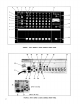
FIGURE 1. SRlOl SERIES 2 AUDIO CONSOLE FRONT PANEL 25 26 29 30 34 32 36 - (SR101 2E Only) 35 37 - (SR101 2E Only) FIGURE 2.
SR101 Series 2 Audio Console OPERATING INSTRUCTIONS FUNCTIONAL IDENTIFICATION (Refer to Figures 1 and 2, Page 2.) NOTE: All push-button switches are "on" when in (depressed) and "off" when out (released). Input attenuator switches are calibrated in decibels; all other front panel controls are numbered for reference only. 1. lndividual Channel Volume Slide Controls (Eight) Control volume and input clipping level of each channel separately. 2.
2. Set all front-panel switches to off (out) and all controls to 0. Set rear-panel PHASE Switch (26) to 0'. 3. Connect desired PROGRAM OUTPUT/LINE LEVEL Connector (25,27) to power amplifier input connecting cable. (NOTE: Shure SR105 Power Amplifiers are supplied with audio connecting cables.) If Console output is to be fed to another mixer or tape recorder microphone input, use PROGRAM OUTPUT/MIC LEVEL Connector (24). If desired, connect monophonic or stereo headphones to front-panel PHONES Jack (8).
operation) or a 0.2-ampere Slo-Blo fuse (for 90- to 132-volt operation). Wired-in 3/10- and 1-ampere fuses protect the ac line and power transformer 5.6-volt secondary winding, respectively. sions given should be followed to provide adequate cable clearance (see Figure 3, Page 5). In either rack- or custom-mounted installations, consider rear-panel access before installation is made.
( TYPICAL OF CHANNELS 1 - 8 1 NOTE l lMlCROPHONE LEVEL I n: 200 HIGH X~~~ 1+23 dB1 , pimq f - 0 - 3 0 dB INPUT ITTEN - CHANNEL VOLUME (SECTION A) - 2 dB CHANNEL EWALIZER - - OUT 4IN f - REVERB INTENSITY (SECTION 0) P / / I , I I f REVERB INTENSITY (SECTION A) / / TONE OSC LEVEL I I - CHANNEL VOLUME (SECTION 0) - I / FEEDBACK - FILTERS] m n RESISTOR [PHASE] m - MASTER VOLUME (SECTION 8) LEVEL . MON LEVEL - / NOTES: I. AUX.
Output Transformer. The Transformer feeds three LlNE LEVEL Output Connectors (25,27) and a MIC LEVEL Output Connector (24), which is at 50 dB below line level. The +6 to $-31 dB Amplifier also feeds the METER SENSITIVITY Control (18), which goes to a +22 dB Meter Amplifier, and then to the VU Meter (17). The Console also contains a 1 kHz Tone Generator for use in set-up and checkout.
creases as the intensity of the reverberant signal is increased. This generally leads to acoustic feedback. However, the SR101 Audio Console reverb mixing system reduces the "dry" signal as the reverb signal is increased; this provides an almost constant gain and reduces the possibility of feedback as reverb is added. The following controls are pertinent to reverb operation. The output of the PROGRAM Switch (13) feeds the channel REVERB INTENSITY Controls (2).
POWER AMPLIFIER PA SPEAKERS LEVEL - SRllO MONITOR MIXER POWER AMPLIFIER STAGE MONITOR SPEAKER I SRllO MONITOR MIXER STEREO RECORDER MONITOR FIGURE 5. SR110 MONITOR MIXER APPLICATIONS PROGRAM MIX AMPLIFIER The program mix amplifier is an active mixing amplifier in which gain remains constant independent of the number of individual channel PROGRAM Switches (13) that are activated. The output of the program mix amplifier is connected through a 560-ohm mixing resistor to the LlNK Jacks (28,31).
If it becomes necessary to use the MIC LEVEL Output Connector (24) to feed a high-impedance input, use a matching transformer such as one of the Shure A95 Series at the high-impedance input. The output of the program output amplifier is also fed to the VU Meter (17) circuit. VU METER CIRCUIT To allow a wide range of signals to be handled by the VU Meter (17), a 22 dB VU Meter amplifier is provided.
BASIC OPERATING HINTS Should any difficulty be encountered in Console operation, the problem may often be traced to some simple source such as an error in interconnection. The following is offered as a basic guide to problems of this sort. Symptom: Console is "dead" (no output, VU Meter lamps out) Check: 1. Check that ac Dower source is "live" and that Console is plugged in. 2. Check that POWER ON-OFF Switch (19) is on. 3. Check to see that rear-panel 3AG-3116A SLO-BLO Fuse (22) is good.
For acoustical-electrified instruments such as classic or folk guitars with pickups and preamplifier outputs, or pianos with pickups and preamplifier outputs, either place the microphone as described above, or connect the pickup to an AUX. LEVEL lnput Jack (32) on the Console. If the cable from the instrument to the Console is greater than 6.lm (20 ft.), use a line matching transformer as described under High-Impedance Microphones (Page 11).
@ , l T l . 5 ~ ~ ~ m ~ , y CHANNEL 7 OR 8 AUX LEVEL INPUT SR lOl AUDIO CONSOLE TURNTABLE 1.5 m @ (5') MAX. P 3 CHAN. I I INPUT FREQ. EQ-LO: + 4 ( FREQ. EQ-HI: * M 6 4 STEREO PREAMPLIFIER U P -6 TO 305 m ) (1000') CHAN. I LOW LEVEL OUTPUT AUX LEVEL INPUT SR lOl AUDIO CONSOLE TURNTABLE ?# ONLY ONE CHANNEL IS USED FOR THIS APPLICATION. FIGURE 9.
A common practice when adding a mixer in this manner is to connect similar-use microphones (for instance, all drum, string or horn microphones) to a single mixer which is fed into the Console. The Console individual channel Volume Control (1) then controls an entire section, facilitating adjustment of that section during a performance.
@ OPTIONAL SLAVE 8 INPUTS 8 INPUTS A A 1111111 OUT LINK "SLAVE" SRlOl AUDIO CONSOLE @ 8 INPUTS OUT LINK 111111I TO POWER AMPLIFIER LINE OUT "MASTER" SRlOl AUDIO CONSOLE 7 INPUTS TO POWER AMPLIFIER AUDIO CONSOLE AUDIO CONSOLE 0 TO POWER AMPLIFIER, BROADCAST LINE. OR TAPE RECORDEE TO HOUSE PA FIGURE 13. ADDITIONAL INPUTS: TWO CONSOLES of one master Console input channel (Figure 13B, Page 15). Connect a cable between the master Console channel 7 (or 8) AUX.
output of one Console, the channel inputs of both units will be routed through the operative Console. This type of system is termed "redundant," that is, the reliability of the system is enhanced through parallel functioning devices. Connect a cable between the LlNK OUT Jacks (31) of each Console. Construct a resistor network as shown in Figure 14, Page 16, and insert it between the LlNE LEVEL Output Jacks (27) on both Consoles and the balanced bridging input of the power amplifier.
the left and right auxiliary outputs of the M688 to the auxiliary inputs of the tape recorder. Before making recordings, adjust the M688 MIC 4 slide control to a midposition for the most desirable balance of vocal microphone levels. REMOTE VOLUME CONTROL A remote volume control may be constructed for' adjusting the output level at a considerable distance from the Console.
SR101 Series 2 Audio Console SERVICE INSTRUCTIONS CONSOLE SERVICE (SEE GUARANTEE, Page 22.) The SR101 Audio Console uses components of the highest quality, operating well within their respective ratings to assure long life. WARNING Voltages in this equipment are hazardous to life. Make all input and output connections with ac power disconnected. Refer servicing to qualified service personnel.
AIO MP12 AI-A9 1 "" "i16 J'" TI-TB R27 RIB - R E 0 J"'/ J12 RIA-R8A BD.5 R168 ~"3"" 1' I"\ " \"" \ s" J17 J21 JII J14 J15 FIGURE 17.
The function of each board assembly is defined in the table below. Component Board No. Function 1 2A 28 3 4 5 6 7 8 9 0 Preamplifier Board ~ ~ u a l i z Boards er (8) Reverb Equalizer Board Program Mix Amplifier Board Reverb Mix Amplifier Board Program Output Board Feedback Filters Board Reverb Spring Amplifier Board Monitor Board Power Supply Board Program Mute Board A magnetic screwdriver is recommended for board fastener removal.
POTENTIOMETERS RIA-RBA, R16A \ SYNCHRONIZING POTENTIOMETERS RIB-R88, R16B SLIDE ACTUATOR / APPROXIMATELY 1/16 IN. PLAY LOWER BEARING ASSEMBLY '-SETSCREW \LOWER PULLEY FIGURE 18. VOLUME CONTROL ASSEMBLY belt, pass it over the upper black plastic bearing assembly, and attach it to the slide actuator. Reassemble the Volume Control assembly as described above.
Insert assemblies for MIC LEVEL Input three-pin, professional, female connectors for channels 2 through 7 (J2-J7) may be removed by first removing the transformer or transformers (TI-T8) mounted above the desired connector. Three-pin, professional, male, audio connector J14 (LINE LEVEL Output) may be removed by first removing the bracket containing the Program Mute board.
SR101 Series 2 Audio Console REPLACEMENT PARTS LIST NOTE: The commercial alternates shown in the following list are not necessarily equivalent parts, but are electrically and mechanically similar, and may be used if direct factory replacements are not immediately available. To maintain highest possible performance and reliability, Shure Factory Replacement Parts should be used. Reference Designation Replacement Kit No.+ Replacement Kit Consists Of: ~ t y . I part NO.
REPLACEMENT PARTS LIST FOR SR101 SERIES 2 AUDIO CONSOLE Reference Designation Replacement Kit No.' Replacement Kit Consists Of: Qty. Part No. Description F1 - - 8081 59 Fuse, Ac, 3AG-3/16A, 125V, Slo-Blo (SRI 01) F1 - - 80C258 80D258 F2 - - 80A267 O.lAT for 220V operation, 0.
REPLACEMENT PARTS LIST FOR SR101 SERIES 2 AUDIO CONSOLE Reference Designation Replacement Kit No.* Commercial Alternate Replacement Kit Consists Of: Qty. - Description Part No.
REPLACEMENT PARTS LIST FOR SRlOl SERIES 2 AUDIO CONSOLE -- Reference Designation Replacement Kit No.' - Replacement Kit Consists Of: Qty. 1 Commercial Alternate Description Part No.
REPLACEMENT PARTS LIST FOR SR101 SERIES 2 AUDIO CONSOLE Reference Designation Replacement Kit No.* Commercial Alternate Replacement Kit Consists Of: Description Part No. Qty. I I Ferrite Bead Ring Stackpole 57-0180; Ferronics 21-030J Transistor, Silicon, Low Power, NPN Motorola 2N5210 Transistor, Silicon, Low Power, PNP Motorola or Fairchild 2N5087 Transistor, Silicon, NPN Motorola 2N5088; TI 2N3711 C200, C201, C205, C208 Capacitor, Electrolytic, 4.
REPLACEMENT PARTS LIST FOR SR101 SERIES 2 AUDIO CONSOLE ~eferensel Desianation Replacement Kit No.' 1 - Replacement Kit Cons;sts Of: I Commercial Alternate REVERB MIX AMPLIFIER (BOARD 4) C400-C402 - C403 - 86A630 Capacitor, Electrolytic, 4.
REPLACEMENT PARTS LIST FOR SR101 SERIES 2 AUDIO CONSOLE Reference Designation Replacement Kit No.* Commercial Alternate Replacement Kit Consists Of: Qty. I Part No.
REPLACEMENT PARTS LIST FOR SR101 SERIES 2 AUDIO CONSOLE Replacement Kit No.* Reference Designation Q700 / RKC12 Replacement Kit Consists Of: I ~tv. I Part No. I 1 1 86A336 I~ransistor,Silicon, NPN Transistor, Silicon, Power, NPN Motorola MPS-U02; GE D40D4 Transistor, Silicon, Power, PNP Motorola MPS-U52; GE D41D4 Transistor, Silicon, NPN MONITOR (BOARD 8) C800, C803, C805, C807, C808 - - Alternate Descri~tion L Motorola 2N5088; TI 2N3711 Capacitor, Electrolytic, 4.
REPLACEMENT PARTS LIST FOR SR101 SERIES 2 AUDIO CONSOLE Reference Designation Replacement Kit No.* Commercial Alternate Replacement Kit Consists Of: Qty. I Part No. I Description PROGRAM MUTE (BOARD 0) C90 - 50KC104 Capacitor, Film, .
FIGURE 20. BOARD 2A: CHANNEL EQUALIZER 2247-21224631587-4 2249-212248-31588-4 FIGURE 21.
FIGURE 22. BOARD 3: PROGRAM MIX AMPLIFIER FIGURE 23.
1818-3/1817-1/482-3 FIGURE 25. BOARD 6: FEEDBACK FILTERS 1827-3/488-3 FIGURE 26.
FIGURE 27. BOARD 8: MONITOR FIGURE 28.
2254-3/592-4 FIGURE 29.
SR101 Series 2 Audio Console NOTES TO CIRCUIT DIAGRAM GENERAL Shure part numbers are not shown in the Parts List accompanying the Circuit Diagram (Figure 31, Page 44) if parts are readily available through local electronics parts suppliers. In these instances, the Circuit Diagram shows only the reference designation and value of the standard parts. All capacitor values are shown in microfarads unless otherwise designated.
10. Reverb circuit measurements made with REVERB INTENSITY Controls full clockwise, and Master Reverb Switch depressed (on). Note that reverb spring and following stages vary with frequency; measurements given are typical only. 11. Monitor circuit measurements made with all MONITOR Switches depressed (on), and PROGRAM MONITOR Switch released (off). 12. Tone oscillator circuit measurements on Program Output (Bd. 5) made with TONE OSC LEVEL Switch on.
ISSUE REFERENCE NUMBER DESCRIPTION -1 94A1293-11-1 2 94A1293-11-2 ADDED R537 FIGURE 32.
ISSUE REFERENCE NUMBER 1 94A1293-11-1 2 94A1293-11-2 DESCRIPTION ADDED R537 (TONE OSCILLATOR) LINE LEVEL (600 1L) FIGURE 32.
SR101 Series 2 Audio Console CONDENSED OPERATING INSTRUCTIONS 1. Set all switches and controls to OFF or 0. 2. Connect PROGRAM OUTPUT (LINE or MIC LEVEL) to power amplifier, broadcast line feed, etc. Connect speakers to power amplifier. Connect headphones to PHONES or MONITOR/LINE LEVEL jack. 3. Connect sources (microphones, tape recorders, etc.) to INPUT Connectors. Set Channel 7 or 8 MIC/AUX Switches as necessary. 4. Connect external signal-processing equipment (compressor, equalizer, etc.) to LlNK Jacks.