SR105 Power Amplifier OPERATION AND SERVICE MANUAL Manufactured by SHURE BROTHERS INC. 222 Hartrey Avenue Evanston, Illinois 60204 U.S.A. WARNING To reduce the risk of fire or electric shock, do not expose this appliance to rain or extreme moisture. Copyright 1979, Shure Brothers Inc. 27A888 (SJ) (95B652) Printed in U.S.A.
SR105 Power Amplifier SPECIFICATIONS The following specifications apply to both SR105A and SR105B Power Amplifiers except where noted. The SR105A Power Amplifier provides both direct-coupled speaker output and transformer-coupled, constant-voltage, 70-volt output. The SRlO5B Power Amplifier is equipped for direct-coupled speaker output only. Amplifier Type . . . . . . . All silicon transistor power amplifier Power Output . . . . . . . .
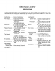
SR105 Power Amplifier SPECIFICATIONS (Curves shown are typical) FREQUENCY (Hz1 OUTPUT POWER (WATTS) TOTAL HARMONIC DISTORTION VS. OUTPUT POWER TO 4-OHM LOAD AT 50 HZ, 1 KHZ & 10 KHz (DIRECT OUTPUT ONLY) OUTPUT POWER VS. FREQUENCY AT 1 % 812% TOTAL HARMONIC DISTORTION TO 4-OHM LOAD (DIRECT OUTPUT ONLY) LOAD RESISTANCE, OHMS OUTPUT POWER (WATTS) TOTAL HARMONIC DISTORTION VS. OUTPUT POWER (VARIOUS LOADS) AT 1 KHz AND CONSTANT 70.
SR105 Power Amplifier TABLE OF CONTENTS Section Page SPECIFICATIONS . . . . . . . . . . . . . . . . . . . . . . . . . . . . . . . i i DESCRIPTION . . . . . . . . . . . . . . . . . . . . . . . . . . . . . . . . . . 1 OPERATING INSTRUCTIONS Functional Identification . . . . . . . . . . . . . . . . . . . . . . . . 3 General Operating Instructions . . . . . . . . . . . . . . . . . . 3 Mounting and Ventilation . . . . . . . . . . . . . . . . . . . . . . . . 4 Thermal Overload . . . . . . . . . . . . . . . . .
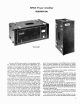
SR105 Power Amplifier DESCRIPTION (Shown in A105A Carrying Case) The Shure SR105 Power Amplifier is a high-power amplifier designed for sound reinforcement applications. It is capsble of delivering 200 watts rms to a 4-ohm load, and is available in two models, the SR105A and SR105B. The SRlO5A Power Amplifier provides both a direct-coupled speaker output and a transformer-coupled constant-voltage, 70-volt output, while the SR105B Power Amplifier is equipped with a direct-coupled speaker output only.
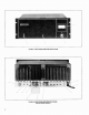
FIGURE 1. SR105 POWER AMPLIFIER FRONT PANEL FIGURE 2.
SR105 Power Amplifier OPERATING INSTRUCTIONS FUNCTIONAL IDENTIFICATION (Refer to Figures 1 and 2, Page 2). 1. OUTPUT VOLTAGE Meter - lndicates Amplifier output voltage in percentage of maximum voltage. 2. VOLUME Control - Controls Amplifier output level. 3. THERMAL OVERLOAD Indicator Lamp - lndicates Amplifier shutdown due to excessive heat sink temperature. 4. POWER ON-OFF Switch - Applies ac power to Amplifier. 5.
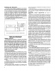
MOUNTING AND VENTILATION The SR105 Power Amplifier is designed for rack-mounting in a standard 19-inch (483 mm) audio equipment cabinet rack and is supplied with the necessary mounting hardware. To insure adequate air circulation, a minimum clearance of 51 mm (2 in.) should be provided above and behind the Amplifier (see Figures 3, Page 4). If the cabinet ambient temperature reaches 43OC (llO°F), forced air ventilation should be provided to avoid the possibility of thermal overload (see following section).
VOLTMETER (70) METER RECTIFIER INPUTS 0'' I' - UNBALANCED METER ADJUST aI DIRECT SPEAKER OUTPUTS / BALANCED BRIDGING 11 ? INPUT XFMR VOLUME / I - LOW-CUT FILTER ASSEMBLY !& '0 d I I I I I !& SRIOSA AMPLIFIER ONLY. = 7 0V I I I I I I I I I I I I I L f 1 1 BALANCE XFMR* * - - -- -- - - - - - - - - - - - - - - 1 I FIGURE 4.
@ UNBALANCED PARALLELED MIXERPREAMPLIFIER POWER AMPLIFIER 0 I I I I I \ A \ / UNBALANCED PARALLELED HIGH-IMPEDANCE INPUTS 0 A- - + I TO POWER AMPLIFIER OR HIGH-IMPEDANCE TAPE RECORDER INPUT TO POWER AMPLIFIER OR OTHER AUXILIARY EQUIPMENT SR105 POWER AMPLIFIER MIXERPREAMPLIFIER @ BALANCED BRIDGING INPUT - 6-TT- SLEEVE 5 570,114 W TIP FIGURE 5.
CAUTION Parallel connection of the DIRECT OUTPUT Connectors (8,9), or the speaker cables between two SR105 Power Amplifiers, or the SR105 Amplifier and any other amplifier, should not be attempted. Balancing paralleled amplifiers is virtually impossible, and the circuitry mismatch cannot be balanced. The same precaution should be observed with regard to the 70V OUTPUT Connectors (11) of two SR105A Amplifiers, or the SR105A Amplifier and any other amplifier.
AMPLIFIER-TO-SPEAKER 200 400 DISTANCE 600 to reduce the wire size in increments as the speaker load becomes less toward the end of the cable run or as branches are split off the main line. The economy of such an arrangement will vary depending upon the details of each installation and should be evaluated accordingly. (FEET1 800 1000 1200 36 i 32 0) 28 Y 2 24 0 Y 1 20 P 3 16 L J I2 0 8 4 0 50 100 1% 200 AMPLIFIER-TO-SPEAKER 250 300 DISTANCE (METERS1 FIGURE 8.
dance may be calculated by the formula: 1 - = ZT 1 - ZI 1 f - + 22 1 - . . . . etc. Z, where ZTis the total impedance, Z, is the impedance of the first speaker, Z, is the impedance of the second speaker, and so forth, with a total number of fractional terms equal to the total number of speakers in the group. Before attempting to add the individual fractions, a common denominator for all fractions must be determined.
Meter Reading Output Power 100% 86.7% 70.7% 50 % 33.3% 10% 1X 3/4X 1/2X 1/4X 1/10X 1/1oox In most applications, the VOLUME Control (2) setting of the Amplifier is determined by the sound level requirements of the area being served. Initial adjustments are made in the audio console feeding the Amplifier to set the average program output level to a value convenient for monitoring on the audio console VU meter, usually 0 VU.
duce approximately 28.3 volts at the DIRECT OUTPUT terminals (8,9), or 70 volts at the 70V OUTPUT terminals (11) when the 70-volt input line is supplying 70 volts. 70-VOLT LINE * 3-PIN MALE AUDIO CONNECTOR ATTENUAm r---i I I - I g I 5 u Part 8 = b - I INPUT FIGURE 10. 70-VOLT SYSTEM ATTENUATOR Recommended Type Phone Jack Phone Plug Volume Control (L-Pad) Transformer, 25V Line to Voice Coil 1 1 1 1 . lr Qty.
SR105 Power Amplifier SERVICE INSTRUCTIONS AMPLIFIER SERVICE (See Guarantee) The SR105 Power Amplifier uses components of the highest quality, operating well within their respective ratings to assure long life. WARNING Voltages in this equipment are hazardous to life. Make all input and output connections with ac power disconnected. Refer servicing to qualified service personnel.
R39 T2 C14 C15 R 31 R40 Dl2 Q8 R35 R36 Q7 R43 PL2 (XPL2) MI PL3 (XPL3) Y SRIOSA MODEL ONLY FIGURE 13. SR105 POWER AMPLIFIER TOP VIEW, COVER REMOVED (SRlOSA MODEL SHOWN) adjustment screw below the meter face until the needle is properly positioned. With no load on the Amplifier (speaker disconnected), connect an ac voltmeter across one of the DIRECT OUTPUT Terminals. Turn the Amplifier on and apply a 1 kHz sine-wave signal at approximately 3 volts rms to one of the Amplifier inputs.
Main Circuit Board Letter Wire Color Letter Wire Color A Blue Black Gray Green/Black Violet Red White White J Yellow/Black Orange/Black Orange Brown Yellow Green White B C D E F G H K L M N P R " 1; Filter Circuit Board ; 2;" Yellow - Yellow/Black - - NOTE: Production variations may result in wire colors differing from those in the table. SMALL SIGNAL AND PREDRIVER TRANSISTORS Transistors Q1 through Q6, Q13, Q14, and Q201 through Q203 are mounted on printed circuit boards.
OUTPUT TRANSISTORS Output transistors Q9 through Q12 (Figure 13, Page 13) are located on the black, finned heat sinks. The replacement procedure is the same as that used for driver transistors Q7 and Q8. NOTE: Output transistors Q9 through Q12 must be matched for current gain. When replacing output transistors, be sure to replace with devices which have the same gain and part number as the original transistors. Shure transistors have a letter suffix in the part number (i.e.
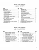
SR105B AMPLIFIER CONVERSION MATERIALS PARTS Qty. Shure Part No. 1 51A244 1 1 1 55C131 56A204 90A2038 Description Qty.
in the space exposed by removal of the cover using four 6-32 x 3h1' Phillips head machine screws. Be sure to orient the screw contacts on the terminal strip in the same manner as the existing DIRECT OUTPUT terminal strip. Mount the slide switch next to the terminal strip in the space provided, using two Phillips round head 4-40 x 3/16" machine screws. Mount the Filter Circuit board next to the Main Circuit board using the four 6-32 x 1/4" Phillips head machine screws previously used to secure the cover.
S4 OFF JI-J2 e TS2 - GROMMET WHT a FILTER CIRCUIT BOARD &- TU x J e d 3 m + t 1 YEL / BLK H& a J RED MAIN CIRCUIT BOARD R41 VOLUME FIGURE 17.
REPLACEMENT PARTS FOR SR105 POWER AMPLIFIER - Reference Designation Replacement Kit. NO.* Replacement Kit Consists Of: Description Part No. Qty. Commercial Alternate Q8 - - 86A362 Transistor, Silicon, PNP, Driver, BVCEO 120V min. Motorola 2N3741 (Selected) Q9-Q12 - 86A360 Transistor, Silicon, NPN RCA 2N3773 R35-R40 45EB439D Resistor, Fixed, 0.43 ohms, 5%, 7W None 46A041 Potentiometer, 50K, VOLUME None - 45CB758C Resistor, Fixed, 7.
REPLACEMENT PARTS FOR SR105 POWER AMPLIFIER Reference Designation Replacement Kit Consists Of: Kit. No.* I 1 RKC9 - 1 4 1 1 / Part No. 86A349 I / 1 Commercial Alternate Descri~tion Transistor. Silicon.
FIGURE 18. MAIN CIRCUIT BOARD PARTS LOCATION DIAGRAM 2038-21525-2 FIGURE 19.
SR105 Power Amplifier NOTES TO CIRCUIT DIAGRAM FIGURE 20. TRANSISTOR LEAD CODES determine that the input and output voltages to each board assembly are correct. If an incorrect ac voltage is found at any board output, perform Dc Voltage Measurements on that board as described below to isolate the problem area. AC VOLTAGE MEASUREMENTS The numbers within rectangular symbols 0on the Circuit Diagram denote the ac voltage at that point under the following test conditions: 1.
LINE LEVEL INPUTS 120 VAC 5 0 1 6 0 Hr NOTE I: DIFFERENCES BETWEEN SRIOSA AND SR105B: "STRAIGHT- THROUGH" WIRING SHOWS SRlOSB CIRCUITS; SRIOSA CIRCUITS INCLUDE ASSEMBLY A2, SWITCH S4, TRANSFORMER T3, AND TERMINAL STRIP TS2. SRIOSB REFERENCE NO. DESCRIPTION -12kb C13 ADDED C17, CIB ADDED R I, R 9 WERE FIGURE 21.
SR105 Power Amplifier CONDENSED OPERATING INSTRUCTIONS DIRECT SPEAKER OUTPUT (MODELS SRlOSA and SRlOSBI I.'with line cord unplugged, install Amplifier in rack or carrying case, allowing adequate ventilation. 2. Connect speakers to DIRECT OUTPUT Jacks and/or Terminal S t r i ~ . 3. Connect con'sole or mixer output to UNBALANCED PARALLELED HIGH IMPEDANCE Input Jack. For cable length greater than 15m (50 ft), use 600-ohm batanced line into BALANCED BRIDGING Input Jack (three-pin). 4.
The Amplifier shall have built-in circuitry to protect the Amplifier from open circuit, short circuit, or mismatched output loads, by using current-limiting, voltage-limiting, temperature-sensing diodes, and thermal-sensing switches. The automatic thermal-sensing switches and temperature-sensing diodes shall be mounted on the output transistor heat sinks to protect the Amplifier from overheating due to short circuits, mismatched output loads, or high ambient temperatures.