Shure Incorporated 222 Hartrey Avenue Evanston IL 60202-3696 U.S.A. UP PORTABLE UHF WIRELESS SYSTEM User’s Guide UP PORTABLE UHF WIRELESS SYSTEM FEATURING THE 2000, Shure Incorporated 27B8681 (TB) UP4 WIRELESS RECEIVER Printed in U.S.A.
ENGLISH ENGLISH TABLE OF CONTENTS QUICK SETUP GUIDE FOR THE SHURE UP WIRELESS SYSTEM . . . . . . . . . . . . . . . . . . . . . . . . . . . . . . . . . . UP4 RECEIVER SETUP . . . . . . . . . . . . . . . . . . . . . . . . . . . . . . . . . . . . . . . . . . . . . . . . . . . . . . . . . . . . . . . . . . . . . . TRANSMITTER SETUP . . . . . . . . . . . . . . . . . . . . . . . . . . . . . . . . . . . . . . . . . . . . . . . . . . . . . . . . . . . . . . . . . . . . . . SYSTEM OPERATION . . . . . . . . . . . .
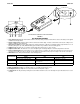
ENGLISH ENGLISH QUICK SETUP GUIDE FOR THE SHURE UP WIRELESS SYSTEM UP4 Receiver Setup and Camera Mounting To audio input To power supply (If not using interior battery power) ATTACHING THE MOUNTING BOX, INSTALLING THE UP4 RECEIVER FIGURE 1 1. Open the battery compartment on the UP4 receiver and insert a fresh 9 volt battery if battery power is to be used. Attach the two antennas to the ANTENNA IN SMA connectors. 2.
ENGLISH UC1 ENGLISH U2 UC2 U1 UP4 UP WIRELESS SYSTEM COMPONENTS FIGURE 2 SYSTEM DESCRIPTION The Shure UP Wireless System is a portable, frequency-agile, diversity wireless system operating in the UHF band. The UP4 receiver is easily mounted to a Sony video camera or any video camera with an Anton-Bauer battery pack. The UP4 is compatible with both Shure UC and UHF Series microphones and body-packs.
ENGLISH ENGLISH 9 8 6 7 10 1 2 3 4 11 UP4 RECEIVER CONTROLS AND INDICATORS 5 FIGURE 3 UP4 RECEIVER FEATURES 1. Group Setting Control. Rotate this switch clockwise to advance the Group setting, or rotate it counterclockwise to decrease the setting. Use the supplied screwdriver to make adjustments. 2. Channel Setting Control. Rotate this switch clockwise to advance the Channel setting, or rotate it counterclockwise to decrease the setting. Use the supplied screwdriver to make adjustments. 3.
ENGLISH ENGLISH 1 2 3 4 1 1 2 2 3 3 4 4 5 6 5 6 8 7 9 7 8 10 11 12 FIGURE 5 FIGURE 4 UC1 TRANSMITTER FEATURES AND CONTROLS UC2 TRANSMITTER FEATURES AND CONTROLS 1. Antenna. A flexible 1/4 wave whip antenna is permanently attached to the top of the UC1 Body-Pack transmitter. 1. Grille. This protects the microphone cartridge and helps reduce breath sounds and wind noise. The grilles for the various microphone heads differ in appearance. 2. Power/Battery Fuel Gauge.
ENGLISH ENGLISH 1 1 3 4 5 1 2 2 7 8 ON OFF 9 6 3 10 GAIN 4 7 8 9 5 10 11 12 13 ON OFF 6 FIGURE 7 FIGURE 6 U2 TRANSMITTER CONTROLS & INDICATORS U1 TRANSMITTER CONTROLS & INDICATORS 1. Antenna. A 1/4 wave antenna is permanently attached to the top of the U1 body-pack transmitter. The antenna can be replaced in the field by a qualified technician. 2. Programmable Display.
ENGLISH ENGLISH CHECKING BATTERIES UP4 Receiver 1. Turn the receiver power ON/OFF switch to the ON position. 2. Observe the PWR LED on front panel (See figure 8). If it is glowing red, the battery power is low and the battery should be changed immediately. PWR LED (Red Indicates Low Receiver Battery) FIGURE 8 UC1 and UC2 Transmitter 1. Turn the transmitter ON/OFF switch to the ON position. 2. Observe the three LED battery gauge (figure 9). Verify that one LED is glowing.
ENGLISH ENGLISH INSTALLING BATTERIES UP4 Receiver Á FIGURE 11 1. Locate the battery door on the bottom of the unit. Release the battery door by sliding the door in the direction of the arrow until the pins on either side of the door are visible. Flip open the battery door once it is released. 2. Insert a fresh 9 volt battery, with terminals facing down, observing the proper polarity (+/–). 3. Return the battery door to its original position and slide the pins back into the lock position.
ENGLISH ENGLISH CHANGING GROUP AND CHANNEL SETTINGS IMPORTANT: Transmitter GROUP and CHANNEL settings must match receiver GROUP and CHANNEL settings. Changing the UP4 Receiver Group/Channel Setting GROUP CHANNEL FIGURE 14 1. To advance the receiver Group or Channel setting, rotate the appropriate switch clockwise, using the supplied screwdriver. Rotate the switch counterclockwise to decrease the setting. Changing the UC1 or UC2 Transmitter Group/Channel Settings FIGURE 15 1.
ENGLISH ENGLISH LOCKING THE POWER ON (U1 AND U2) B A FIGURE 18 1. To lock the power on, press and hold the SET button, then press and hold the MODE button. Hold both keys down until “PoL” (for power locked) is displayed, as shown in Figure 18A. NOTE: When the Power On Lock function is activated, “–– ––” will flash on the transmitter screen every 5 seconds when the transmitter power ON/OFF switch is in the OFF position. 2.
ENGLISH ENGLISH UP4 RECEIVER SET UP Attaching The UP4 Receiver Antennas FIGURE 20 1. Center the antenna over the SMA Antenna Input Connectors on the front panel of the receiver. 2. Rotate the antenna in a clockwise direction until the base of the antenna is threaded firmly to the connector. Attaching the Mounting Box to a Camera A FIGURE 21 1. Locate the battery pack (A) on the camera.
ENGLISH ENGLISH INSTALLING THE UP4 RECEIVER Side Mounted Rear Mounted To Power Supply (if not using battery power) To Audio Input FIGURE 23 1. After the mounting box is attached to the camera, insert the UP receiver in the box. It should slide in easily, but fit snuggly. 2. Connect XLR audio output on the bottom of UP receiver to audio input on the camera. 3. If not using internal 9V battery power, connect the DC jack on the bottom of the UP receiver to an external power supply (see Power Cable).
ENGLISH ENGLISH ATTACHING THE WEATHER-RESISTANT COVER FIGURE 24 1. Join the narrow ends of the two sections of the weather–resistant cover using the attached Velcro as shown. FIGURE 25 2. Wrap the joined pieces of the weather cover around the UP4 Receiver BEFORE inserting the UP4 into its mounting bracket. 3. Join the wide ends of the pieces over the control panels, using the attached Velcro strips. 4. Insert the UP4 receiver into the mounting bracket (see Installing the UP4 Receiver). 5.
ENGLISH ENGLISH OPERATING THE UP SYSTEM WITH UC1 OR U1 BODY–PACK 1. If the UP4 receiver has not been mounted to the camera, attach the mounting box (See Attaching Mounting Box) and install the UP4 receiver, connecting the XLR output on the receiver to the sound input on the camera (See Installing UP4 Receiver). Set the Push-Lock Audio Gain Pot to the appropriate level for the camera sound input or other equipment you are using.
ENGLISH ENGLISH CHANGING THE TRANSMITTER SETTINGS Adjusting the Transmitter Gain Level The U1, U2, UC1 and UC2 transmitter audio gain level has been factory preset to provide satisfactory output in most applications, and it will probably not need to be adjusted for most microphone applications. However, for loud talkers, the preset level may be too high, as indicated by a constant glow of the red audio LED on the receiver.
ENGLISH ENGLISH TIPS FOR ACHIEVING OPTIMUM PERFORMANCE • Maintain a line of sight between the transmitter and receiver antennas. • Use the proper receiver antennas. • Do not obstruct the receiver antennas. • Avoid operating near metal objects. • Never use two transmitters set to the same frequency concurrently. • Keep distance between transmitter and receiver as short as possible.
ENGLISH ENGLISH BODY-PACK TRANSMITTER SPECIFICATIONS UC1 U1 Input Configuration UA, UB: 50 mW Typical MB: 50 mW Typical KK: 50 mW Typical Unbalanced, active UA, UB: 10 mW Typical MB: 10 mW Typical KK: 10 mW Typical Unbalanced Connector Type 4-pin Tini QG (male) 4-pin Tini QG (male) Actual Impedance 18 kΩ 18 kΩ Connector Pin Assignments Pin 1:Tied to Ground Pin 2:Tied to +5 V Pin 3:Tied to Audio Pin 4:Tied to 20kΩ Resistor and Audio Ground RF Output 9 V alkaline battery (Duracell MN1604 recom
ENGLISH ENGLISH COMPONENT DIMENSIONS UP4 124.6 mm L x 85.1 mm W x 31.8 mm T (4 58/64“ x 3 11/32“ x 1 1/4”) WEIGHT UC1 99.2 mm L x 63.5 mm W x 23.0 mm D (3 UC2/58 241.3 mm L x 50.8 mm Dia. (9 1/2” x 2”) UC2/87 215.9 mm L x 50.8 mm Dia. (8 1/2” x 2”) U1 98.4 mm L x 64.7 mm W x 24.6 mm D (3 U2/58 254 mm L x 50.8 mm Dia. (10” x 2”) U2/87 15/ 229 mm L x 49.2 mm Dia. (9” x 1 29/ 32” x2 1/ 2” x 29/ 353.8 g (11.4 oz) 32”) 73.5 g (2.59 oz) without battery 311.