
Specifications

7
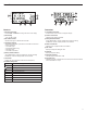
RF Power
Reference the following table for setting RF Power:
RF Power Setting
System
Range
Application
1 mW 33 m (100 ft.)
For increased channel reuse
at close distances
10 mW 100 m (330 ft.) Typical setups
20 mW 100 m (330 ft.)
For hostile RF environments
or long-distance applications
Note: Using the 20 mW setting decreases the transmitter battery runtime
and reduces the number of compatible systems.
Interference Detection
Interference Detection analyzes the quality of the RF signal and detects in-
terference conditions that have caused an audio signal dropout. When inter-
ference is identified, the RF LEDS illuminate red and the following warning
displays on the receiver LCD panel.
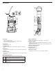
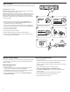
RF
ULXD4
Digital Wireless Receiver
sync
push
control
ENTER
EXIT
SCAN
RF
A B
OL
OL
gain power
audio
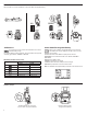
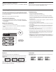
Setting Gain
Adjust gain at the receiver so that the average signal levels are solid green and yellow with peaks that flicker the red overload LED. Attenuate the gain if the
signal overloads repeatedly.
Set the XLR output to line-level when possible to optimize sound system noise performance.
ULXD4
Digital Wireless Receiver
sync
push
control
ENTER
EXIT
SCAN
RF
A B
OL
OL
gain poweraudio
RF
AB
L
OL
gain poweraudio
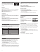
Adjusting Gain
Pressthe▲▼
gain buttons on the front of the receiv-
er to incrementally adjust gain from -18 to +42 dB.
Large Gain Adjustments
RF
A B
OL
OL
gain poweraudio
ULXD4
Digital Wireless Receiver
sync
push
control
ENTER
EXIT
SCAN
OL
Press and hold a
gain button
or
Use the control wheel in
the
AUDIO menu
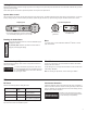
Transmitter Input Clip
The following warning displays on the receiver LCD panel when the trans-
mitter input is clipped:
Mic. Offset
Use this to compensate for signal level differences between transmitters
that share the same receiver.
Set the offset gain on a low signal level transmitter to match a louder trans-
mitter:
Utility > Mic.Offset
Note: For normal gain adjustments, use the receiver gain buttons.
System Gain Control
The gain control on the receiver sets the audio signal level for the entire system. This allows adjustments to be made during a live performance. It is not nec-
essary to change the gain on the transmitter (mic offset) to optimize the gain structure. Any required changes to gain should be made from the receiver.
Mute
To mute the audio, use Shure Wireless Workbench
®
software or a third-
party control device.
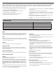
Reading the Audio Meter
To correct, attenuate the signal source. If the source
cannot be attenuated while using a bodypack transmit-
ter, select INPUT PAD from the main menu to attenuate
the input signal 12 dB.
Tx OVERLOAD
Perform a Scan and Sync during a perfor-
mance break if the warning display persists
or the audio drops out repeatedly.
Audio peaks illuminate the LEDs for 2 seconds while RMS signal
is displayed in realtime.
OL (Overload) LED: Illuminates red when the internal limiter is
engaged, preventing digital clipping.