XPC Bios User Guide For the : SH61R5 Series
Shuttle® XPC Installation Guide Copyright ©2012 by Shuttle® Inc. All Rights Reserved. No part of this publication may be reproduced, transcribed, stored in a retrieval system, translated into any language, or transmitted in any form or by any means such as electronic, mechanical, magnetic, optical, chemical, photocopy, manual, or otherwise, without prior written permission from Shuttle® Inc.
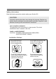
Safety Information Read the following precautions before setting up a Shuttle XPC. CAUTION Incorrectly replacing the battery may damage this computer. Replace only with the same or equivalent as recommended by Shuttle. Disposal of used batteries according to the manufacturer's instructions. Laser compliance statement The optical disc drive in this server is a laser product. The drive's classification label is lacated on the drive. CLASS 1 LASER PRODUCT CAUTION:NVISIBLE LASER RADIATION WHEN OPEN.
TABLE OF CONTENTS Driver and Software Installation........................................................1 Mainboard Driver DVD ..................................................................1 User Manuals . ........................................................................2 Appendix...........................................................................................3 Starting BIOS.................................................................................3 BIOS Setup Menu..............
English Driver and Software Installation Motherboard Driver DVD The DVD contents attached in SH61R5 Series motherboard are subject to change without notice. The Motherboard Driver DVD contains all the motherboard drivers necessary to optimize the performance of this Shuttle Xvision in a Windows® OS. Install these drivers after installing Microsoft® Windows®. Insert the attached DVD into your DVD-ROM drive. The DVD AutoRun screen should appear.
English User Manuals Install Adobe Reader 9.
English Appendix Starting BIOS AMIBIOS has been integrated into many motherboards for over a decade. In the past, people often referred to the AMIBIOS setup menu as BIOS, BIOS setup, or CMOS setup. American Megatrends refers to this setup as BIOS. Specifically, it is the name of the AMIBIOS8 BIOS setup utility. This chapter describes the basic navigation of the BIOS setup screens. Enter the BIOS To enter the BIOS setup screens, follow the steps below: Step1. Power on the motherboard. Step2.
English AMIBIOS8 has default text messages built into it. The motherboard manufacture retains the option to include, leave out, or change any of these text messages. They can also add their own text messages. Because of this, many screen shots in this manual are different from your BIOS setup screen. The BIOS setup/utility uses a key-based navigation system called hot keys. Most of the BIOS setup utility hot keys can be used at any time during the setup navigation process.
English Main Setup When you first enter the BIOS Setup Utility, you will enter the Main setup screen. You can always return to the Main setup screen by selecting the Main tab. There are two Main Setup options. They are described in this section. The Main BIOS Setup screen is shown below. System Time/System Date Use this option to change the system time and date. Highlight System Time or System Date using the keys. Enter new values through the keyboard.
English Advanced Select the Advanced tab from the BIOS setup screen to enter the Advanced BIOS Setup screen. You can select any of the items in the left frame of the screen, such as CPU Configuration, to go to the sub menu for that item. You can display an Advanced BIOS Setup option by highlighting it using the keys. All Advanced BIOS Setup options are described in this section. The Advanced BIOS Setup screen is shown below. The sub menus are described on the following pages.
English Power Management Configuration ACPI Sleep State Select the highest ACPI Sleep state the system will enter when the SUSPEND button is pressed. The choice: S1 (CPU Stop Clock) , S3(Suspend to RAM). EuP Control Function Enable or disable system EuP function in S4/S5. The choice: Enabled , Disabled. PWR-On After PWR-Fail Enable or disable system power on automatically after AC power restored. The choice: Enabled , Disabled.
English Wake On Onboard LAN Enable or disable system wake on by onboard LAN chip. The choice: Enabled , Disabled. Wake Up By Ring Enable or disable system wake up by Ring. The choice: Enabled , Disabled. Wake Up By USB3.0 Port Enable or disable system wake up by USB3.0 Port. The choice: Enabled , Disabled. CPU Configuration You can use this screen to select options for the CPU Configuration Settings. Use the up and down keys to select an item.
English Hyper-threding Enabled for Windows XP and Linux (OS optimized for Hyper-Threading Technology) and Disabled for other OS (OS not optimized for Hyper-Threading Technology). When Disabled only one thread per enabled core is enabled. The choice: Enabled , Disabled. Active Processor Cores Number of cores to enable in each processor package. The choice: ALL,1,2,3. Limit CPUID Maximum Disabled for Windows XP and later OSes. The choice: Enabled , Disabled.
English SATA Configuration SATA Mode (1) IDE Mode. (2) AHCI Mode. Hot Plug Enable or disable Hot Plug capability. The choice: Enabled , Disabled.
English Onboard Device Configuration Initate Graphic Adapte Select which graphics controller to use as the primary boot device. The choice: PCI-E Onboard VGA / Onboard VGA. Onboard VGA Memory Onboard VGA Share Memory Size. The choice: 32M,64M,128M,256M,512M. Azalia HD Audio Enable or disable system Azalia HD Audio. The choice: Enabled , Disabled. USB3.0 Controller Enable or disable onboard USB3.0 chip. The choice: Enabled , Disabled. Onboard LAN Chip Enable or disable onboard LAN chip.
English USB Configuration 12
English Super IO Configuration COM1 Enable or disable system COM1. The choice: Enabled , Disabled. Charge Settings Change settings for COM1. The choice: IO=3F8h,IO=2F8h,IO=3E8h,IO=2E8h. CIR Controller Enable or disable system CIR Controller. The choice: Enabled , Disabled.
English H/W Monitor PC Health Status Fan1 Speed Control Fan1 Speed Control function. The choice: Smart Fan Speed , Ultra-Low Mode, Low Mode , Mid Mode , Full Mode. Fan2 Speed Control Fan2 Speed Control function. The choice: Smart Fan Speed , Ultra-Low Mode, Low Mode , Mid Mode , Full Mode.
English Voltage Configuration VDIMM Voltage Set VDIMM Voltage Set Parameter. The choice: Auto , +50mv , +100mv , +150mv. SB 1.05 Voltage Set SB 1.05 Voltage Set Parameter. The choice: Auto , +50mv , +100mv , +150mv.
English Boot Select the Boot tab from the BIOS setup screen to enter the Boot BIOS Setup screen. You can select any of the items in the left frame of the screen, such as Boot Settings Configuration, to go to the sub menu for that item. You can display an Boot BIOS Setup option by highlighting it using the keys. All Boot BIOS Setup options are described in this section. The Boot BIOS Setup screen is shown below. The sub menus are described on the following pages.
English BIOS Write Protect Enables/Disables BIOS Write Protect control function. The choice: Enabled , Disabled.
English Security Select the Security tab from the BIOS setup screen to enter the Security BIOS Setup screen. You can display an Security BIOS Setup option by highlighting it using the keys. All Security BIOS Setup options are described in this section. The Security Setup screen is shown below. The sub menus are documented on the following pages.
English Select Change User Password to give or to abandon password setting same as Change Supervisor Password item above. Note that Supervisor Password field allows users to enter and change the settings of the BIOS SETUP UTILITY, while User Password field only allows users to enter the BIOS SETUP UTILITY without having the authorization to make any change. The Password Check item is used to specify the type of BIOS password protection that is implemented.
English Save & Exit Select the Exit tab from the BIOS setup screen to enter the Exit BIOS Setup screen. You can display an Exit BIOS Setup option by highlighting it using the keys. All Exit BIOS Setup options are described in this section. The Exit BIOS Setup screen is shown below.
English Save Changes and Exit When you have completed the system configuration changes, select this option to leave BIOS Setup and reboot the computer so the new system configuration parameters can take effect. Select "Save Changes and Exit" from the Exit menu and press . Save Configuration Changes and Exit Now? [Ok] [Cancel] appears in the window. Select Ok to save changes and exit. Discard Changes and Exit Exit system setup without saving any changes.