XPC BIOS User Guide For the : XS36V4
Shuttle® XPC Installation Guide Copyright ©2013 by Shuttle® Inc. All Rights Reserved. No part of this publication may be reproduced, transcribed, stored in a retrieval system, translated into any language, or transmitted in any form or by any means such as electronic, mechanical, magnetic, optical, chemical, photocopy, manual, or otherwise, without prior written permission from Shuttle® Inc.
Safety Information Read the following precautions before setting up a Shuttle XPC. CAUTION Incorrectly replacing the battery may damage this computer. Replace only with the same or equivalent as recommended by Shuttle. Dispose of used batteries according to the manufacturer's instructions. Laser compliance statement The optical disc drive in this server is a laser product. The drive's classification label is lacated on the drive. CLASS 1 LASER PRODUCT CAUTION: INVISIBLE LASER RADIATION WHEN OPEN.
TABLE OF CONTENTS Driver and Software Installation........................................................1 Motherboard Driver CD..............................................................1 User Manuals.............................................................................2 Appendix...........................................................................................3 Starting BIOS..............................................................................3 BIOS Setup Menu...................
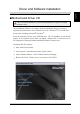
English Driver and Software Installation Motherboard Driver CD The CD contents attached in XS36V4 motherboard are subject to change without notice. The Motherboard Driver CD contains all the motherboard drivers necessary to optimize the performance of this Shuttle Xvision in a Windows® OS. Install these drivers after installing Microsoft® Windows®. Insert the attached CD into your CD-ROM drive. The CD AutoRun screen should appear.
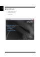
English User Manuals Install Adobe Reader 9.
English Appendix Starting BIOS AMIBIOS has been integrated into many motherboards for over a decade. In the past, people often referred to the AMIBIOS setup menu as BIOS, BIOS setup, or CMOS setup. American Megatrends refers to this setup as BIOS. Specifically, it is the name of the BIOS setup utility. This chapter describes the basic navigation of the BIOS setup screens. Enter the BIOS To enter the BIOS setup screens, follow the steps below: Step1. Power on the motherboard. Step2.
English Has default text messages built into it. The motherboard manufacture retains the option to include, leave out, or change any of these text messages. They can also add their own text messages. Because of this, many screen shots in this manual are different from your BIOS setup screen. The BIOS setup/utility uses a key-based navigation system called hot keys. Most of the BIOS setup utility hot keys can be used at any time during the setup navigation process.
English Main Setup When you first enter the BIOS Setup Utility, you will enter the Main setup screen. You can always return to the Main setup screen by selecting the Main tab. There are two Main Setup options. They are described in this section. The Main BIOS Setup screen is shown below. System Time/System Date Use this option to change the system time and date. Highlight System Time or System Date using the keys. Enter new values through the keyboard.
English Advanced Select the Advanced tab from the BIOS setup screen to enter the Advanced BIOS Setup screen. You can select any of the items in the left frame of the screen, such as CPU Configuration, to go to the sub menu for that item. You can display an Advanced BIOS Setup option by highlighting it using the keys. All Advanced BIOS Setup options are described in this section. The Advanced BIOS Setup screen is shown below. The sub menus are described on the following pages.
English Power Management Configuration Wake Up by USB (S3) Enable or disable system wake up by USB (S3). The choice: Enabled , Disabled. EuP Function Enable or disable system EuP function in S4/S5. The choice: Enabled , Disabled. PWR-On After PWR-Fail Enable or disable system power on automatically after AC power restored. The choice: Power Off, Power On, Former-Sts, Power On by LAN and Power On by RTC.
English Wake Up by Ring Enable or disable system wake up by Ring. The choice: Enabled , Disabled. Wake Up by LAN Enable or disable system wake on by onboard LAN chip. The choice: Enabled , Disabled. PowerOn by RTC Alarm When enabled, System will wake on the hr::min::sec specified. The choice: Enabled , Disabled. CPU Configuration You can use this screen to select options for the CPU Configuration Settings. Use the up and down keys to select an item.
English The CPU Configuration setup screen varies depending on the installed processor. C State Support This item allows you to enable or disable the CPU C state function. The choice: Enabled , Disabled. Active Processor Cores Number of cores to enable in each processor package. The choice: All,1. Intel (R) V. T. When enable, a VMM can utilize the additional hardware capabilities provided by vanderpool Technology. The choice: Enabled , Disabled.
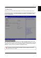
English OnBoard Device Configuration High Definition Audio This item allows you to enable or disable the HD Audio. The choice: Enabled , Disabled. OnBoard LAN Function (+ SD Card) This item allows you to enable or disable the onboard LAN function. The choice: Enabled , Disabled. Onboard LAN Boot ROM This item allows you to enable or disable the onboard LAN boot ROM. The choice: Enabled , Disabled. IGD Memory Size Select Onboard IGD Graphics Memory Size. The choice: 64MB,128MB,256MB,512MB.
English Serial Port Configuration Serial Port 1 / Serial Port 2 Enable or disable system Serial Port 1 / Serial Port 2. The choice: Enabled , Disabled. Change settings COM1 mode select. The choice: RS232, RS422, RS485 Serial Port 1/2 Address The choice: IO=3F8h,IO=2F8h,IO=3E8h,IO=2E8h.
English SATA Configuration SATA Mode SATA mode select. The choice: IDE, AHCI.
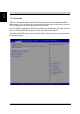
English USB Configuration USB 3.0 Controller Set this value to allow the system to enable or disable the onboard USB 3.0 Controller. The choice: Enabled, Disabled. USB 2.0(EHCI) Support Set this value to allow the system to enable or disable the onboard USB 2.0 Controller. The choice: Enabled, Disabled.
English 14 Hardware Health Configuration
English Boot Select the Boot tab from the BIOS setup screen to enter the Boot BIOS Setup screen. You can select any of the items in the left frame of the screen, such as Boot Settings Configuration, to go to the sub menu for that item. You can display an Boot BIOS Setup option by highlighting it using the keys. All Boot BIOS Setup options are described in this section. The Boot BIOS Setup screen is shown below. The sub menus are described on the following pages.
English Security Select the Security tab from the BIOS setup screen to enter the Security BIOS Setup screen. You can display an Security BIOS Setup option by highlighting it using the keys. All Security BIOS Setup options are described in this section. The Security Setup screen is shown below. The sub menus are documented on the following pages. Flash Write Protection Enabled/Disabled BIOS Write Protection control function. The choice: Enabled , Disabled.
Select Change User Password to give or to abandon password setting same as Change Supervisor Password item above. Note that Supervisor Password field allows users to enter and change the settings of the BIOS SETUP UTILITY, while User Password field only allows users to enter the BIOS SETUP UTILITY without having the authorization to make any change. The Password Check item is used to specify the type of BIOS password protection that is implemented.
English Secure Boot Menu Secure Boot Secure boot enable/disable. The choice: Enabled , Disabled. Secure Boot Mode Secure boot mode select. The choice: Standard Custom.
English Save & Exit Select the Exit tab from the BIOS setup screen to enter the Exit BIOS Setup screen. You can display an Exit BIOS Setup option by highlighting it using the keys. All Exit BIOS Setup options are described in this section. The Exit BIOS Setup screen is shown below. Save Changes and Exit When you have completed the system configuration changes, select this option to leave BIOS Setup and reboot the computer so the new system configuration parameters can take effect.