
User's Manual


File Doc. No. Date Version Page
DBHB-20 5700 9004 055 Nov. 05 1.0 6/13
Next Generation
Signal Enhancement
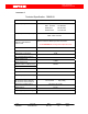
4.0 Description of DBHB-20 Booster installation Kit
The DBHB-20 booster system contains an automatic power control, bi-
directional amplifier (BDA) supplied along with a donor antenna (highly directive
outdoor antenna) and server antenna (indoor omni directional antenna),
specifically designed for interior configurations. The donor antenna must be
pointed toward the cell of the base station from where the signal is to be picked
up and is usually mounted on the exterior of the building so as to receive the
maximum forward signal level from the base station. The indoor antenna of
DBHB-20 booster provides RF signal in all directions downward and outward
from the installation point.. A adopter is supplied with DBHB-20, powered by
universal 90/270 VAC mains supply. A standard length of 30 ft. RF coaxial cable
with connectors is supplied to connect the donor antenna and DBHB-20 booster.
Any other RF coaxial cable length is also available optionally, on request.
.
Figure 4.0 : Installation Diagram of Home Booster
List of Installation Kit
1. Donor Antenna – Patch Antenna (Optional 7 dbi)
2. Server Antenna - Whip Antenna. (Optional 0 dbi )
3. RF coaxial cable with N to SMA (M) connector. (Optional)
4. Booster DBHB-20.
5. AC/DC Adapter (9VDC/3.0 Amp.).
6. Mounting Kit.
7. Installation and Operational Manual
Donor Antenna
Coaxial Cable
+9V DC
AC/DC
Adapter
Donor Antenna