OPERATION MANUAL Digital COLOR ECHO SOUNDER CVS-128 CVS-128.OM.
Declaration of Conformity (As referred to in Annex IV 2. of Directive 2004/108/EC) Declares under his sole responsibility that the produced Echo Sounder manufactured by Koden Electronics Co., Ltd.
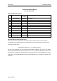
CVS-128 Revision History CVS-128 Operation Manual Doc No. 0093112802 Document Revision History No. Doc. No-Rev. No. Date Revised Revised Content (Y/M/D) 0 0093112802-00 2009/05/27 First edition 1 2 3 4 5 6 7 8 9 10 Document No. Revised Version Norm When part of the document needs to be revised, the document has advanced revision number. The document No. is indicated at the lower right side on the cover and at the left or right side of the footer region of each page. © 2009 Koden Electronics Co.
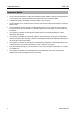
Important Notice CVS-128 Important Notice • The re-use and transcription of Instruction Manual (hereafter called this manual) needs permission of our company. Our company prohibits the un-authorized re-use and transcription. • If this manual is lost or damaged, consult our dealer or our company. • The specification of our products and the content in the Instruction Manual are subject to changed without notice.
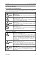
CVS-128 For Your Safe Operation For Your Safe Operation Pictorial used in this Instruction Manual This Instruction Manual uses the following pictorials. Understand the meaning of each pictorial and implement the maintenance and inspection. Symbol Meaning Mark for warning This symbol denotes that there is a risk of death or serious injury when not dealing with it correctly.
For Your Safe Operation CVS-128 Caution on location of equipment Do not install the equipment where it is excessively damp and suffers from excessive water drops. Escaping from static electricity The static electricity may be generated from the carpet on the floor in the cabin or clothes made of synthetic fiber. The static electricity may destroy the electronic parts on the circuit board. Handle the circuit board, taking the measure of static electricity free.
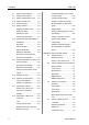
CVS-128 Contents Contents Document Revision History....................ⅰ Basic Operation of Gain............. 1-8 Important Notice .....................................ⅱ Selecting the auto gain .............. 1-9 For Your Safe Operation ........................ⅲ Adjusting the gain by auto ......... 1-9 Contents .................................................ⅴ Selecting the manual gain ......... 1-9 Introduction.............................................. ⅷ Manual adjustment of the gain...
Contents CVS-128 2.7 Setting of Zoom Range ..............2-4 Change the display color of echo 2.8 Setting of Zoom Start .................2-4 sounder image ......................... 2-15 2.9 Setting of Background Color ......2-5 Change the depth value ........... 2-15 2.10 Setting of White Line ..................2-5 Display the water temp graph / 2.11 Preset of Range .........................2-5 Stop the display of water temp 2.12 Setting of Alarm ..........................2-6 graph .........
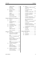
CVS-128 Contents Local time Offset ........................ 3-3 3.5 5.4 GPS select ................................. 3-3 Connection of Cable to CVS-128 GPS initialize.............................. 3-3 Display unit ................................ 5-8 Maintenance Menu .................... 3-4 Pin Assignment of Rear Simulation .................................. 3-4 Connector .................................. 5-8 Slide show.................................. 3-4 Connection of Power Cable .......
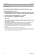
Introduction CVS-128 Introduction The CVS-128 is a Dual frequency (50 kHz/200 kHz) Color LCD display echo sounder. This unit equipped with digital process displays the circumstance in the water under all conditions, matching with the high luminance 8.4 inch LCD. The main features of this unit are as follows: • With the digital reception process, the compatibility of the high resolution in a shallow depth and the noise rejection capability in a deep depth are established.
CVS-128 System Configuration System Configuration Legend Connection Diagram CVS-128 Display unit Standard configuration Option Prepared by a user With mounting bracket and hard cover To External monitor connector (J7 connector) To Transducer connector (J6 connector) To POWER connector External monitor (Prepared by a user) CW-576-0.
Configuration of Equipment CVS-128 Configuration of Equipment Standard Equipment Configuration List No 1 Name of item Weight/ Length Quantity 600 W/1 kW output with mounting bracket and knob 3.2 kg 1 250 g 1 2m 1 Display unit CVS-128 2 Remark Type Hard cover E57MB11060 3 4 5 DC power cable (Complex cable) CW-264A-2M With 12 connector at one end/ un-treated at the other end F-7161-3A Cylinder (ø 6.
CVS-128 Configuration of Equipment Type of transducer No Specification Frequency Material / Length of the cable Mounting method Beam width (Right and left x back and forth) Plastic Inner-hull (The inner-hull kit is needed.) 50kHz 50°x50° ( -6dB) 200kHz 17°x17° ( -6dB) Through-hull 50kHz 50°x50° ( -6dB) 200kHz 17°x17° ( -6dB) TD-500T-2B 50/200 kHz 600 W 1 9m TD-500T-3B 50/200 kHz 600 W 2 TD-501C 3 50/200 kHz 1 kW Bronze 9m Rubber mold 10m Inner-hull (The inner-hull kit is needed.
CVS-128 Chapter 1 Basic Operation Chapter 1 Basic Operation 1.1 How to use the key CVS-128 Display unit 1 2 3 4 5 6 7 8 9 10 In addition, for your convenience when operating keys other than keys in the menu by the [MENU] key, the menu displayed automatically closes. No. 1 Key Name Explanation [F1] Recalls directly the item preset. 2 [EVENT] Notifies the external equipment of the present position. Presets the menu. It begins a fishing hot spot. 3 [Cursor] Selects the menu item.
Chapter 1 Basic Operation CVS-128 How to remove the hard cover While widening the claws at right and left sides of hard cover, draw the hard cover towards you. Claw When removing CVS-128 Display unit To prevent dust from entering, cap the connector at the rear of CVS-128 Display unit and the power cable with caps. Install the supplied cap to the transducer cable as shown in the figure and cap it. Caution: Do not pull the cable strongly. If you do so, it will be broken.
CVS-128 Chapter 1 Basic Operation Explanation of the display: 1.2 Power On/Off Function icon Rainbow pattern Alarm icon Time mark Event icon Range Gain Power on 1 Press the [BRILL ] key to power on. The startup menu is displayed. When started up, the memories (ROM, RAM) are automatically checked. When checking is normally finished, the menu below is displayed.
Chapter 1 Basic Operation CVS-128 Disp 1.3 LCD Brilliance Adjustment NAV1 Normal (H) Zoom (H) Dual Freq Zoom (L) Normal (L) NAV2 Adjustment of LCD Brilliance The brilliance of the display can be adjusted to facilitate visualization. The [Lcd brill] and [Panel brill] can be switched every time when pressing the [BRILL ] key. 1 Press the [BRILL ] key for a short period of time to display the menu ([Lcd brill]). (H): High frequency 2 Rotate the [GAIN (HF) Knob] or [GAIN (LF) Knob].
CVS-128 Chapter 1 Basic Operation Dual frequency The High frequency image can be displayed in the right half side and the Low frequency image can be displayed in the left half side. Since the beam width differs depending on frequency, the schools of fish and sea bottom look different. Low frequency image High frequency image Zoom (Low frequency, High frequency) A part of normal image can be zoomed. (1) [BTM.] (Bottom), (2) [B.D.] (Bottom Discrimination), (3) [Zoom], (4) [B.Z.] (Bottom Zoom) and (5) [B.
Chapter 1 Basic Operation CVS-128 The display width of zoom is displayed in orange. (1) Bottom Normal image Zoomed range 30.0 Zoom image (2) Bottom Discrimination The display width of zoom is displayed in orange. Normal image Zoomed range 30.0 Zoom image The display width of zoom is displayed in orange. (3) Zoom Normal image Zoom start position Zoomed range 30.
CVS-128 Chapter 1 Basic Operation The display width of zoom is displayed in orange. (4) Bottom Zoom Normal image Zoomed range 30.0 Zoom image The image below the bottom is not zoomed. (5) Bottom Follow Zoom The display width of zoom is displayed in orange. Normal image Zoomed range 30.0 Zoom image Navigation Menu (NAV1, NAV2) The navigation menu can be displayed at the left side on the display. To display the information other than depth, sensors need to be connected. (See [2.
Chapter 1 Basic Operation CVS-128 1.5 Switch-over of Range Setting the range switching to Manual range The range of measured depth displayed on the display can be changed. The range can be manually selected: 1 Press [▲] or [▼] key of [▲RANGE▼]. To meet your purpose, select the range of measured depth. 2 Select the range you desire to set. (Press [▲] or [▼] key of [▲RANGE▼]) Range Setting the range switching to auto range Auto range 5.0 10.0 50.0 80.0 100.0 150.
CVS-128 Caution: When only high frequency is displayed, no gain adjustment at low frequency is available. When only low frequency is displayed, no gain adjustment at high frequency is available. Chapter 1 Basic Operation Selecting the manual gain Adjustment of gain can be done manually. 1 Caution: The low frequency can be set by [GAIN (LF) Knob]. Selecting the auto gain When the [Cruising] or [Fishing] is set, the gain can be fine-adjusted.
Chapter 1 Basic Operation 4 Press the [MENU] to close the menu. CVS-128 Preseting the destination The present set value of frequency (High frequency or Low frequency) adjusted last is displayed at the upper left side of menu. When you find the school of fish or tide, its location can be preset as a destination. (10 locations at maximum) Example: The High frequency gain is 8.0 → H: 8.0. When presetting the destination, switch [System] → [EVENT Key set] → [Store pos]. (See [1.
CVS-128 Chapter 1 Basic Operation Store the image L When you find the schools of fish, its location can be stored as a destination. (10 locations at maximum) H When storing the image, switch [NAV] → [EVENT Key set] → [Store pos]. (See [1.7 Use of [EVENT] key. Selecting the event].) 1 Press the [EVENT] key. Processing 2 Cursor (Red line) is displayed. After a certain time passes, the image of echo sounder presently displayed is stored and the list number of stored image is displayed.
Chapter 1 Basic Operation CVS-128 Fishing hot spot Leads you back to your favorite fishing hot spots or other previously stored positions in memory with input from optional GPS sensor. (See [2.13 Preset/ WPT edit/ WPT delete of Destination]) L H To perform the fishing hot spot, it is necessary to select [System] → [EVENT key set] → [Fishing hot spot]. (See [1.7 Use of [EVENT] key Selecting the event]) 1 In the state that no other key is pressed, press the [ ] key or the [ ] key.
CVS-128 Chapter 1 Basic Operation Preset of [F1] / [F2] key 1 2 3 4 Press the [MENU] key. Select [System] → [F1 key set] or [F2 key set]. (Press the [ ] key or [ ] key or [ ] key.) (See [2.1 How to operate the menu]) Press the [ ] key. Marker Depth 20.0 Movable marker Select the function.
Chapter 1 Basic Operation CVS-128 1.10 Display of fish information 2 Select [Disp] → [Symbol info]. (Press the [ ] key or [ ] key or [ ] key.) (See [2.1 How to operate the menu]) Specific response can be displayed as [Fish symbol]. 3 4 Press the [ ] key. By [Symbol info], the magnitude and the value of depth of the response can be displayed. Select the information associated with [Fish symbol] (Press the [ ] key or [ ] key.
CVS-128 Chapter 1 Basic Operation Points to note in use of fish symbol The values displayed by this function may be incorrect depending on various environmental conditions. In use of these values, please understand the following factors of error, and use them as reference: 【Factors of error】 】 1 When there are overlapping responses, all of them may be displayed to show the magnitude of a point.
CVS-128 Chapter 2 How to use the menu Chapter 2 How to use the menu 2.1 How to operate the menu Adjust D.range Disp Alarm1 Alarm2 NAV Image Sonar System Next Display the menu/Stop the display of menu 1 Press the [MENU] key. The menu and explanation of operation are displayed. Cursor Name of menu selected Menu column Setting item column Setting value Adjust D.
Chapter 2 How to use the menu CVS-128 7 To select the menu name of other, press the [ ] key. The cursor returns to the menu column. 2.3 8 Press the [MENU] key to close the menu. Interference Rejection 2.2 Changing of Image Speed The image speed of echo sounder can be changed. Even if the schools of fish and bottom are same, the image changes depending on the image speed. The setting of image speed is shown by the comparison with the normal image speed “1/1”.
CVS-128 2.4 Chapter 2 How to use the menu Color Rejection of Weak Echo 5 2.6 Press the [MENU] key to close the menu. Setting of Shift Color Rejection The color of weak echo can be rejected. Rejecting noise on the entire image and weak echo around the school of fish makes it easier to see the school of fish. It is the convenient function when displaying the echo stronger than the specific signal. (Setting: 0 ~ 50 %) 1 2 Press the [MENU] key. 3 4 Press the [ ] key.
Chapter 2 How to use the menu CVS-128 Setting of Auto Shift (Setting: m: 2.5 to 200, fm, I.fm: 2.5 to 150, The image is automatically shifted so that the bottom is always displayed. ft:10.0 to 650) 1 2 Press [▲] of [▼] key of [▲RANGE▼]. Select the[Auto shift](Press [▲] of [▼] key of [▲RANGE▼]) Zoom Range Range Auto range 5.0 10.0 20.0 50.0 100 160 300 500 Auto shift Range 1 Press the [MENU] key. 2 Select [D. Range] → [Zoom range]. (See [2.1 How to operate the menu]) 3 Press the [ ] key.
CVS-128 Chapter 2 How to use the menu How to operate the menu]) 3 4 Press the [ ] key. Change the set value of [Zoom start]. (Press the [ ] key or [ ] key) Zoom start 10 0~800 5 2.9 m White line Press the [MENU] to close the menu. Setting of Background Color 1 2 Press the [MENU] key Select [Disp] → [White line]. (See [2.1 How to operate the menu]) Responding to the ambient brightness, the background color of display can be changed. 1 2 Press the [MENU] key. 3 4 Press the [ ] key.
Chapter 2 How to use the menu [ ] key) Adjust D.range Disp Alarm1 Alarm2 NAV Image Sonar System Next [Water temp alarm] issues when the water temp is within or out of the set range. It is convenient to keep the specific water temp region. (Setting: - 5 to 45 ℃, 23 to 113 ºF) Prev Range 1 Range 2 Range 3 Range 4 Range 5 Range 6 Range 7 Range 8 Return 5.0 m 10.0 m 20.0 m 50.0 m 100 m 160 m 300 m 500 m Caution: Select [Forward], and press [ ] key to return to the previous menu. 5 6 Press the [ ] key.
CVS-128 Chapter 2 How to use the menu Setting the alarm Confirm the alarm state Adjust D.range Disp Alarm1 Alarm2 NAV Image Sonar System Next Adjust D.range Disp Alarm1 Alarm2 NAV Image Sonar System Next Lower depth OFF 5m 50m Fish alarm Position OFF 5m Range Level Return 50m Medium Bottom alarm Upper depth The set state of [Bottom alarm] and [Fish alarm] can be confirmed on the bar at the right corner of display. However, when the display is out of the range, they are not displayed.
Chapter 2 How to use the menu 2.13 Preset/WPT edit/WPT delete of Destination CVS-128 Cancel the NAV The NAV started can be canceled halfway. 1 Press the[MENU] key NAV Start 2 The NAV can be started by selecting the destination from the destination list. Select [NAV] → [NAV cancel]. (See [2.1 How to operate the menu]) 3 Press the [ ] key. 4 Press the [Yes]. (Press the [ ] key or [ ] key) To perform the NAV start, the destination must be preset. (See [1.
CVS-128 key. (Character: A ~ Z, blank, 0 ~ 9, +, -./) Chapter 2 How to use the menu 2 Select [NAV] → [WPT delete]. (See [2.1 How to operate the menu]) 7 3 4 Press the [ ] key. 5 Press the [ ] key. 6 Select the [Yes] in the confirmation menu. (Press the [ ] key or [ ] key) Select the list number of destination to be deleted from the [WPT delete]. (Press the [ ] key or [ ] key) Move the position of characters to be reversed with the [ ] key or [ ] key. WPT delete Yes No 7 Press the [MENU] key.
Chapter 2 How to use the menu 2.14 Store / Recall / Deletion of Image Image recall No. 1 2 3 4 5 6 7 8 9 10 Comment PIC0 0 0 01 PIC0 0 0 02 PIC0 0 0 03 PIC0 0 0 04 PIC0 0 0 05 PIC0 0 0 06 PIC0 0 0 07 PIC0 0 0 08 PIC0 0 0 09 PIC0 0010 Store the image The present image of echo sounder can be stored. To memorize, it takes some time. To memorize the image, the [EVENT] key must be switched to the [Store image]. 1 2 Caution: Chosen list NO. becomes yellow. 5 6 CVS-128 Press the [ ]key.
CVS-128 Image recall No. Comment 1 PIC0 0 0 0 1 2 PIC0 0 0 02 PIC0 0 0 03 3 4 PIC0 0 0 04 PIC0 0 0 05 5 PIC0 0 0 06 6 PIC0 0 0 07 7 PIC0 0 0 08 8 PIC0 0 0 09 9 10 PIC0 0 010 Chapter 2 How to use the menu 6 Select the [Yes] in the confirmation menu. Image delete Yes No 7 Press the [MENU] key. Then, the preset image is deleted. Caution: Chosen list NO. becomes yellow. 5 Press the [ ] key. Caution: When other stored image exists beside the recall image, switch to other image with the [ ] and [ ] key.
Chapter 2 How to use the menu 7 Select the comment position with the [ ] key or [ ] key. CVS-128 2.16 Selection of NAV Display Image comment Selection of NAV Display No. Comment 1 P I C 00 00 1 2 P I C 00 002 P I C 00 003 3 The information can be displayed on the NAV display (NAV 1, NAV2). 8 To stop editing, press [GAIN (HF) Knob] or [GAIN (LF) Knob]. 9 After finishing the edit, press the [MENU] key. Caution: Requires position data from GPS sensor.
CVS-128 Chapter 2 How to use the menu Selection of NAV Menu 2.17 Explanation of Sonar 1 2 Press the [DISP] key. Switch-over of Sona-tone 3 [NAV1] is displayed at the right side. Select the [NAV1] or the [NAV2]. (Press the [ ] key or [ ] key) Disp NAV1 Normal (H) Zoom (H) Dual freq Zoom (L) Normal (L) NAV2 4 5 The schools of fish and condition of bottom on the display of echo sounder can be confirmed by hearing the sonar. NAV1 Display1 Display2 Display3 Display4 1 2 Press the [MENU] key.
Chapter 2 How to use the menu CVS-128 2.18 Explanation of Menu Item TVG The various items in the menu are explained. The TVG adjusts the difference of strength between echoes reflected from the shallower depth and echoes reflected from deeper depth so that the reflection can be uniformed. Inner-hull The reduction in sensitivity due to signal attenuation in inner-hull use can be corrected. (Setting: - 50 ~ 50: through-hull: 0) 1 2 Press the [MENU] key. Select the [Adjust] → [Gain (TD)]. (See [2.
CVS-128 1 Press the [MENU] key 2 Select the [Adjust] → [TX power]. (See [2.1 How to operate the menu]) 3 Press the [ ] key. 4 Select the [TX power]. (Press the [ ] key or [ ] key.) Chapter 2 How to use the menu Change the display color of echo sounder image The [Monochrome], [8 color], [16 color] and [64 color] can be selected. 1 2 Press the [MENU] key. 3 4 Press the [ ] key. TX power 20 1 30 40 50 60 70 80 90 100 Auto 5 Press the [MENU] key to close the menu.
Chapter 2 How to use the menu CVS-128 display width can be changed. 4 1 2 Press the [MENU] key. Select the swap state. (Press the [ ] key or [ ] key) 5 Press the [MENU] key to close the menu. 3 4 Press the [ ] key. 5 Select the [D.range] → [Disp. width]. (See [2.1 How to operate the menu]) Select the width of image. (Press the [ ] key or [ ] key) Press the [MENU] key to close the menu.
CVS-128 Chapter 3 How to use the menu2 Chapter 3 How to use the menu2 3.1 Display of Menu After powering on, besides the menu displayed first with the [MENU] key, the system menu, of which setting is not frequently changed, is provided. [In out], [Correct], [Setting], [Maintain] Display the menu 1 Press the [MENU] key. 2 Select the [Next]. Adjust D.range Disp Alarm1 Alarm2 NAV Image Sonar System Next 3 3.2 Setting of External Input / Output Set the setting related to the input/output.
Chapter 3 How to use the menu2 NMEA Monitor CVS-128 3.3 Setting of Correct Item The external input data can be displayed. To return to the original menu, press the [MENU] key. Caution: When [GAIN (HF) Knob] is pressed, the displayed data will stop. NMEA Output Data Prev In out Correct Setting Maintain Draft set 0.0m Sonic speed Seawater Water temp Boat speed 0.0℃ Beam width H 17° Beam width L 50° 0% Return The output of NMEA sentence can be set to ON/OFF.
CVS-128 3.4 Chapter 3 How to use the menu2 Setting of Basic Set Item GPS initialize It is valid only when KODEN GPS is connected. Prev In out Correct Setting Maintain Language English Range&Speed unit NM,kn m Depth unit Temperature unit ℃ Localtime offset GPS select GPS initialize Return The GPS sensor is initialized. Caution: When connecting the GPS sensor other than KODEN GPS, do not use this item. . 0.0 Others No Language Switch to the language to be displayed.
Chapter 3 How to use the menu2 3.5 Maintenance Menu CVS-128 All stored image deletes All stored image lists can be deleted. Prev In out Correct Setting Maintain Simulation OFF Slideshow Initialize OFF No System check All WPTs:DLT All IMG DT:DLT Return Simulation When the [Simulation] is set to ON, the pseudo image of echo sounder is displayed. Slide show The slide show of the images stored in [Image]→ [Image recall] is available.
CVS-128 Chapter 4 Maintenance and Inspection Chapter 4 Maintenance and Inspection 4.1 Inspection The daily maintenance and inspection extends the life of equipment. To always keep the equipment in the best condition, implement periodically the inspection shown in the table below. Item Content of Inspection Connector at the rear of CVS-128 Display unit Check the looseness. Wiring of cables Check the wiring of cables connecting the equipment and the damage of cable.
Chapter 4 Maintenance and Inspection CVS-128 4.3 Fuse Replacement Warning Use the specified fuse. If you use a fuse other than specified one, it may lead to a serious accident. If the input voltage is too high, the over-current flows or a trouble occurs inside, the fuse will blow out. The fuse is housed in the power cable. 4.4 If you suspect a trouble Symptom Trouble cause Countermeasure Even if the power is powered on, nothing is displayed. • Blown fuse.
CVS-128 Chapter 4 Maintenance and Inspection 4.5 Diagnostic Test Perform the operation diagnosis. Confirm the version When checking the operation diagnosis of panel key, the state of sensor inside and the version of software, it is using. ③ displays the information on the version of software. When inquiring, inform us of ver XX.XXX. Return to the menu Press the [MENU] key for more than 3 seconds. Diagnose ① displays the diagnostic result.
CVS-128 Chapter 5 Installation Chapter 5 Installation 5.1 Item of Caution on Installation To exercise fully the performance of echo sounder, the installation of CVS-128 must be performed by an engineer who is officially authorized by our company. The installation work includes the following content.
Chapter 5 Installation CVS-128 Laying and Connection of Cable (1) Keep the transducer and power cable as far away from the cables of other electronic equipment as possible. (2) The cabinet of CVS-128 Display unit is securely grounded to the hull, using the ground terminal on the rear panel. Caution: The ground side of power input of this equipment is connected to the ground terminal. In case of + (positive) ground, it cannot be used. The power may short-circuit.
CVS-128 Chapter 5 Installation 5.2 Installation of CVS-128 Display unit CVS-128 Display unit can be desk-top installed or flush-mount installed. Install in the following procedure. Desk-top Installation (1) Remove two knob bolts fixing the display unit to the bracket. (2) Remove the display unit from the bracket and place it on the stable flat place. (3) Place the bracket on the position where the display unit will be installed and fix the bracket with five 5 mm screws.
Chapter 5 Installation CVS-128 Caution: When installing on the desktop, the maintenance space shown in the illustration below is required for cable lay-out, plugging-in/out of connector, fuse replacement and bolt tightening. 100 240 100 (3 15/16) (9 29/64)) (3 15/16) Unit: mm (inch) Fig. 5.
CVS-128 Chapter 5 Installation Flush-mount Installation (1) Make a square hole (220mm x 220mm) at the location to be installed. (See Fig. 5.5.) (2) Turn counter-clockwise the knob bolt fixing the display unit to the mounting bracket to loosen it, push the unit to the left side and pull the unit upward. The mounting bracket and knob bolt are no longer used. (3) Confirm that the unit matches with the square holes. If not matched, correct the square hole.
Chapter 5 Installation CVS-128 5.3 Installation of Transducer The standard installation of this echo sounder is shown in figure 5.6. Figure 5.6 Installation of Transducer In case of Inner-hull Using the optional inner-hull kit (MFB-04), install the transducer to the inner side of ship’s bottom. Caution on installation (1) Select the location where no bubble is generated during navigation. (2) Select the relatively thin location of ship’s bottom. (3) Be sure to remove oil on the contact surface.
CVS-128 Chapter 5 Installation In case of through hull Install the transducer directly to the ship’s bottom Installation Procedure (1) Select the installing location. (2) Remove the fixing nut and one piece of rubber packing. (3) If the slope of ship’s bottom is greater than 5°, make a wooden base to fit to the slope of ship’s bottom. To reduce the water resistance, cut the bow direction tip of wooden base at the outer side of ship’s bottom in the triangle shape.
Chapter 5 Installation CVS-128 5.4 Wiring Connection of Cable to CVS-128 Display unit Connect the power cable and transducer to the connectors of CVS-128 Display unit. Power input 10.8~31.
CVS-128 Chapter 5 Installation Connection of Power Cable Connect the power cable to the [POWER] connector and the transducer to the [J6] at the rear of CVS-128 Display unit connector. Connection of DC power cable (CW-264A-2M) To [POWER] connector 3.5 stereo jack DC+ (Red) DC- (Black) Caution: Wind the insulation tape around the un-used lead wire for core-wires not to contact each other. Grounding • Use heavy gauge cable for grounding wire.
Chapter 5 Installation CVS-128 Connection of Transducer At the end to the transmission/receiving cable for TD-500T-2B, TD-500T-3B and TD-501T-3B, a water proof connector with 8-core is provided. At the end to the transducer for TD-501C is plain. 1) TD-500T-2B/500T-3B/501T-3B Connect to the J6 connector on the back of the receiver display unit. 2) TD-501-C The user must have the cable, CW-840-0.3M (option)for the transducer. Solder the transducer to CW-840-0.
CVS-128 Chapter 5 Installation Connection with external equipment The DC power cable contains the connection cables for external equipment such as navigation equipment and KODEN GPS sensor.
Chapter 5 Installation CVS-128 Connection with Speed Sensor or Water Temperature Sensor (Option) When installing the optional speed sensor or water temperature sensor, connect to the [J6] connector together with the transducer via the transducer cable (Type: CW-840-0.3M). For wiring, see the figure below. After soldering, implement the waterproof and insulation treatment on the connected part with the self-melting tape.
CVS-128 Chapter 5 Installation Connection of External Speaker for Sone-Tone (Prepared by a customer) The ø3.5 stereo jack is provided to the power cable. If you connect the speaker with the amplifier to the external, you can clearly hear the sona-tone sound. Adjust the volume of speaker with the amplifier equipped to the speaker 3.5 stereo jack Connection of External Monitor (J7) (Prepared by a customer) When installing an external monitor (VGA monitor, analog RGB input), connect it via CW-576-0.5M.
Chapter 5 Installation CVS-128 5.5 Serial Data Input Data The sentences of GGA, GLL, HDT, MTV, MWV, RMC, VHW, VTG and ZDA can be received. The type of NMEA0183 Ver.1.5, Ver.2.0 and Ver.3.0 can be inputted.
CVS-128 Chapter 6 Table Attached Chapter 6 Table Attached 6.1 Menu List The factory set value is shown by the bold and underline. 【Disp】key NAV1, Normal (H), Zoom (H), Dual freq, Zoom (L), Normal (L), NAV2 Disp 【▲RANGE▼】key RANGE Auto range, 5.0, 10.0, 20.0, 50.0, 100, 160, 300, 500, Auto shift 【GAIN(HF)】,【GAIN(LF)】 Gain select Manual, Cruising, Fishing Auto adjust - 10 to 10 (H): 0, (L): 0 Gain 0.0 to 10.0 (H): 6.0, (L): 6.
Chapter 6 Table Attached CVS-128 【MENU】key Adjust Image speed (2/1, 1/1, Stop, 1/1.5, 1/2, 1/2.5, 1/3, 1/3.5, 1/4, 1/4.5) IR (OFF, Weak, Strong) Color rejection (0 to 50 %: 0% %) Noise rejection (0 to 10: 0) TVG (Weak, Medium, Strong) TX power (20, 30, 40, 50, 60, 70, 80, 90, 100, Auto) Gain (TD) (-50 to 50: H: 0, L: 0) D.range Shift (0 to 300m: 0m) Zoom type (Bottom, Bottom Discrimination, Zoom, Bottom Zoom, Bottom Follow Zoom) Zoom range (2.5 to 200 m: 10.
CVS-128 Chapter 6 Table Attached A Alarm 2 Water temp alarm (OFF, ON (Inside), ON (Outside)) Upper temp alarm (- 5 to 45.0 ℃: 20.0 ℃) Lower temp alarm (- 5 to 45.0 ℃: 15.0 ℃) Speed alarm (OFF, ON (Upper), ON (Lower)) Speed limit (0 to 80 kn: 0 kn) Arrival alarm (OFF, ON) XTE alarm (OFF, ON) NAV alarm range (5 to 999 m: 10 m) NAV NAV start (No.1 to No.10) NAV cancel (Yes, No) WPT edit (No.1 to No.10) WPT delete (No.1 to No.
Chapter 6 Table Attached CVS-128 B Setting Language (English, Japanese, etc) Range&Speed unit (NM, ,kn, km, km/h) Depth unit (m, fm, I.fm, ft) Temperature unit (℃ ℃, °F) Localtime offset (- 11.0 to 14.0: 0.
CVS-128 Chapter 6 Table Attached 6.2 Specification Serial Data Display unit Overall Item Model Transmission Frequency Transmission Method Transmission Power Content CVS-128 50 kHz/200 kHz Single or alternate 600 W/1 kW Transmission Firing Times Transmission Pulse Width Minimal Reception Gain Display Display Mode Zoom Mode 8.
Chapter 6 Table Attached CVS-128 Plane view 6.
CVS-128 Chapter 6 Table Attached Maintenance Space 100 240 100 (3 15/16) (9 29/64)) (3 15/16) Unit: mm (inch) Dimension drawing of table installation 240 (9 29/64) 220 (8 21/32) Hole for installing 4-4mm screw R2 5 (6 3/ 64 ) Threading hole 224 (8 5/32) Unit: mm (inch) Dimension drawing of flush-mount installation 0093112802-00 6-7
11001 Roosevelt Blvd., Suite 800 St. Petersburg, FL 33716 Tel: 727-576-5995 Fax: 727-576-5547 www.si-tex.