
User's Manual
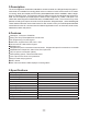


6.Installation
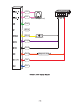
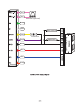
7.Wiring
Pink
Pink
Green
White
Yellow
Red
Black
Blue
Purple
Orange
Remove the back cover from the keypad using the supplied special screw driver
Drill 2 holes on the wall for the self tapping screws and dig a hole for the cable
Put the supplied rubber bungs into the two holes
Fix the back cover firmly on the wall with 2 self tapping screws
Thread the cable through the cable hole
Attach the keypad to the back cover.
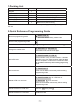
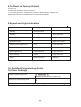
Colour
BELL_A
BELL_B
D0
D1
OPEN
12V+
GND
NO
COM
NC
Function Description
Doorbell button one end (optional)
Doorbell button to the other end (optional)
WG output D0
WG output D1
Exit button one end(the other end connected GND)
12V + DC Regulated Power Input
12V - DC Regulated Power Input
Relay normally-on end(Connect positive electric lock "-")
Relay Public end, connect GND
Relay Closed end(connect negative electric lock "-")