
User's Manual


6XEMHFWWRFKDQJHZLWKRXWQRWLFHSICK AGWaldkirchGermanywww.sick.com 5 ) 8 ; _ 6 , & . 3
3. Establish a connection between SOPAS ET and RFU620 via
the wizard which opens automatically. In order to do this,
select the desired communication interface for searching
in the connection wizard. (Default Ethernet address: IP
address: 192.168.0.1, Subnet mask: 255.255.255.0)
SOPAS ET establishes communication with the RFU620
DQGORDGVWKHDVVRFLDWHGGHYLFHGHVFULSWLRQÀOHIRUWKH
RFU620. The
Q
UICKSTART tab opens.
b. Detecting a transponder in Quickstart mode
1. Bring one or more standards-compliant UHF transponders
into the working area of the RFU620 antenna. The UII/EPC
of the individual transponders must be different so that
multiple transponders can be detected.
2. In SOPAS ET, in the
Q
UICKSTART tab, click the START button.
SOPAS ET generates an automatic reading cycle and
lists the detected transponders one after another in the
Quickstart window.
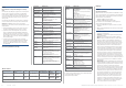
SOPAS ET: Display of several detected transponders in the QUICKSTART
window
,QWKHGHIDXOWFRQÀJXUDWLRQWKHEOXHOLJKWRXWSXWRIWKH
process feedback LEDs (5) in the corners of the RFU620
DQWHQQDFRYHULQGLFDWHVZKHWKHUD8+)ÀHOGLVSUHVHQWDQG
transponders have been detected.
Light output of the LEDs
in Quickstart mode
Meaning
Lights up with medium intensity
8+)ÀHOGSUHVHQW
+LJKLQWHQVLW\VORZÁDVKLQJ
WUDQVSRQGHULQÀHOG
+LJKLQWHQVLW\UDSLGÁDVKLQJ
RUPRUHWUDQVSRQGHUVLQÀHOG
Important!
The automatic triggering in Quickstart mode is intended for
(initial) commissioning and not for permanent use when
operating the RFU620 under real conditions.
c. Accessing the data on a transponder
1. In order to access the memory area of a transponder, in
Q
UICKSTART click the STOP button.
2. Mark the desired transponder (click it with the mouse).
3. Click the
T
RANSPONDER ACCESS button.
The
T
AG ACCESS tab now displays the content of the select-
ed transponder.
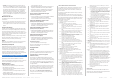
SOPAS ET: TAG ACCESS display window
Important!
7KH7,'7DJ,GHQWLÀHURIWKHWUDQVSRQGHUFDQQRWEH
changed.
d. &RQWLQXLQJWKHFRQÀJXUDWLRQSURFHVV
1. In the SOPAS ET navigation tree on the left, edit the
required RFU620 tabs for the application using the addi-
tional entries under
P
ARAMETERS.
7KHVHLQFOXGHDQWHQQDFRQÀJXUDWLRQÀOWHUIXQFWLRQV
transponder processing, object trigger control (e.g. via
"Sensor 1" switching input), data processing, data output,
interfaces, function of the switching inputs and outputs,
and the possible use of an optional Micro-SD memory
card.
2. On the
A
NTENNA CONFIGURATION tab, the transmitting power
for the antenna can be set using sliders.
&RQÀJXUDWLRQ: Example setting for the internal antenna
RFU620 default setting:
Transmitting power: 15 dBm (30 mW)
3. 7HVWDQGLIQHFHVVDU\PRGLI\WKHVSHFLÀHGVHWWLQJVZKHQ
operating the system under real conditions.
e. &RPSOHWLQJWKHFRQÀJXUDWLRQSURFHVV
> 3HUPDQHQWO\VDYHWKHHQWLUHFRQÀJXUDWLRQRQFHLWKDVEHHQ
successfully tested:
Parameter set in the RFU620: Click the
button
&RQÀJXUDWLRQÀOHRQWKH3&&OLFNWKH
button.
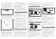
Device description
Device layout
71.9
76.9
69.7
71.9
55.3
7
RFU620-101xx
RFU620-101xx
RFU620-104xx
RFU620-105xx
RFU620-105xx
RFU620-104xx
25.5
71.9
76.7
0
30
116
20.1
0
25
20.1
0
25
113.9
103.3
20.1
34.4
0
50
100°
All dimensions in mm
18.1
0
54
130.8
137.4
130.8
6 x 7.7 (= 46.2)
1
3
4
8
5
6
2
à
â
á
1
“Power/AUX/CAN/I/O” connection
(17-pin M12 plug, A-coded)
2 “Ethernet” connection (4-pin M12 socket, D-coded)
3 “PoE” connection (8-pin M12 socket, X-coded)
4
”Power/HOST/AUX/CAN/I/O” connection
(15-pin D-Sub HD plug, cable 0.9 m)
5 4 x LED multi-color (Process Feedback)
6 7 x LED (status indicators)
7 Cover with integrated antenna
8 2 x screws (Torx T8), captive, for lateral cover
9 USB socket, type Micro-B
ß Slot for micro SD card
à 4 x threaded mounting holes M5, 9 mm deep, alternatively
for mounting the RFU620
á Pressure compensation valve (ventilation element)
â 2 x threaded mounting holes M6, 7 mm deep, or mounting
the RFU620
9
ß
Lateral
cover
opened
7