
User guide

16
SR80/185T - SR100/185T 1..0 - 20
optional
M
+
-
12V
5A
red
black
yellow
Terminator
120 ohm
Terminator
120 ohm
Retract
panel
Power supply
cable
Retract
thruster
Controller
6 1242
T-connector T-connector T-connector
Actuator
Draw no:
Drawn:
Sleipner Motor AS
P.O. Box 519
N-1612 Fredrikstad
Norway
Tel: +47 69 30 00 60
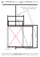
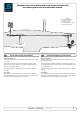
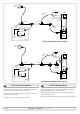
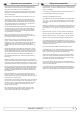
Wiring Retract thruster
W / manual main switch
L.G. 8.6.09
RTS-A00-652-01
Battery
+12V
8730
Foot
Switches
( opt.)
Remote control
(opt.)
Manual main switch
Main fuse
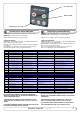
The S-link control system is powered by a dedicated power cable con-
nected to the system backbone as a normal spur cable.
The cable ends connect to battery pos. and battery neg. and the cable
shield connects to battery neg.
The battery pos. must be connected through a 5A fuse.
N
GB
S-link systemeter strømforsynt via en dediker strømkabel som kobles til
systemets “backbone” som en normal “spur”-kabel.
Kabelendene kobles til batteriets pluss- og minuspol og skjermkabelen
kobles til batteriets minuspol.
Ledningen som kobles til batteriets plusspol må sikres med en 5A sikring
M
+
-
12V
5A
red
black
yellow
Terminator
120 ohm
Terminator
120 ohm
Retract
panel
Power supply
cable
Retract
thruster
Controller
6 1242
T-connector T-connector T-connector
Actuator
Draw no:
Drawn:
Sleipner Motor AS
P.O. Box 519
N-1612 Fredrikstad
Norway
Tel: +47 69 30 00 60
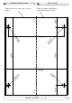
Wiring Retract thruster
W / Automatic Main Switch
L.G. 8.6.09
RTS-A00-651-01
Battery
+12V
Automatic
Main Switch
w/S-link
8730
Foot
Switches
( opt.)
Remote control
(opt.)
optional
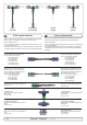
S-link koblingsskjema
S-link system schematics
Setup with manual main switch
Setup with automatic main switch