
User's Manual


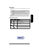


Table Of Contents
- Table of Contents
- SITRANS LR 460
- Specifications
- Installation
- Wiring
- 4-20 mA Start Up
- Local Operation
- LCD menu structure
- HART Communications
- Remote operation via PROFIBUS PA
- PROFIBUS PA Profile Structure
- Appendix A: Parameter Descriptions
- 1. Identification
- 2. Input
- 3. Output
- 5. Maintenance settings
- 6. Condensed Status Setup
- 6.1. Condensed Status Mode
- 6.1.1. Loss of Echo S0 (Status; Diagnosis)
- 6.1.2. Cable Fault S1 (Status; Diagnosis)
- 6.1.3. No Tech Power S2 (Status; Diagnosis)
- 6.1.4. Device Lifetime Maintenance Required Limit S3 (Status; Diagnosis)
- 6.1.5. Device Lifetime Maintenance Demanded Limit S4 (Status; Diagnosis)
- 6.1.8. Sensor Lifetime Maintenance Demanded Limit S7 (Status; Diagnosis)
- 6.1.9. Device Service Maintenance Required Limit S8 (Status; Diagnosis)
- 6.1.10. Device Service Maintenance Demanded Limit S9 (Status; Diagnosis)
- 6.1.11. LTB Scale S10 (Status; Diagnosis)
- 6.1.12. Internal Temp Sensor S11 (Status; Diagnosis)
- 6.1.13. Internal Temp High S12 (Status; Diagnosis)
- 6.1.16. AIFB2 PV Range S15 (Status; Diagnosis)
- 6.1.19. Calibration Schedule Maintenance Demanded Limit S18 (Status; Diagnosis)
- 6.1.30. Memory EEPROM S29 (Status; Diagnosis)
- 6.1.31. Memory EEPROM Flags S30 (Status; Diagnosis)
- 6.1.32. Memory Flash S31 (Status; Diagnosis)
- 6.1.33. Ident Violation S32 (Status; Diagnosis)
- 6.1.34. Internal Temperature Calibration S33 (Status; Diagnosis)
- 6.1. Condensed Status Mode
- Appendix B: Technical Reference
- Appendix C: Troubleshooting
- Appendix D: Maintenance
- Appendix E: Software Revision History
- Glossary
- Index

7ML19985JM01 SITRANS LR 460 – INSTRUCTION MANUAL Page 3
mmmmm
SITRANS LR 460
Application Examples
The application example used in this manual illustrates a typical installation using
SITRANS LR 460. Because there is often a range of ways to approach an application,
other configurations may also apply. If the example does not apply to your application,
check the applicable parameter reference for the available options.
If you require more information, please contact your Siemens Milltronics representative.
For a complete list of Siemens Milltronics representatives, go to www.siemens.com/
processautomation.
Abbreviations and Identifications
Note: This equipment has been tested and found to comply with the limits for a Class A
digital device, pursuant to Part 15 of the FCC Rules. These limits are designed to provide
reasonable protection against harmful interference when the equipment is operated in
a commercial environment. This equipment generates, uses, and can radiate radio
frequency energy and, if not installed and used in accordance with the instruction
manual, may cause harmful interference to radio communications. Operation of this
equipment in a residential area is likely to cause harmful interference, in which case
the user will be required to correct the interference at his own expense.
WARNING: Changes or modifications not expressly approved by
Siemens Milltronics could void the user’s authority to operate the
equipment.
Short
form
Long Form Description Units
A/D Analog to digital
AIFB Analog Input Function Block
CE / FM /
CSA
Conformitè Europèene /
Factory Mutual / Canadian
Standards Association
safety approval
C
i
Internal capacitance
D/A Digital to analog
DAC Digital Analog Converter
DCS Distributed Control System control room apparatus
FV Full Vacuum
ESD Electrostatic Discharge
I
i
Input current mA
I
o
Output current mA
IS Intrinsically Safe safety approval
L
i
Internal inductance mH
LR Level Radar
LTB Level Transducer Block
mH milliHenry 10
-3
Henry