
Installation Guide

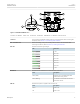
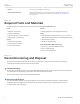
Table Of Contents
- RUGGEDCOM WIN5137-V
- Table of Contents
- Preface
- 1. Introduction
- 2. Installing the Subscriber Unit
- 3. Device Management
- 4. Technical Specifications
- 5. Certification

RUGGEDCOM WIN5137-V
Installation Guide
Chapter 1
Introduction
Description 3
4
3
1
8
6
5
7
2
RSSI
W.LINK PWR
Figure1:RUGGEDCOM WIN5137-V
1.ETH Port 2.PWR Port 3.ANT 1 Port 4.ANT 2 Port 5.RSSI LEDs 6.W.LINK LED 7.PWR LED 8.Chassis Ground
12VDC Port A 4-pin, female, D-Coded M12 port for power. For more information about connecting data
and power, refer to Section2.7, “Connecting Power and Data”.
ANT 1 and ANT 2 Ports Ports for connecting primary and secondary external antennas. For information about
connecting the antennas, refer to Section2.5, “Installing the Antennas”.
RSSI LEDs Indicates the received signal strength.
LED RSSI Level
< -90
-85 to -90
-80 to -85
-75 to -80
-70 to -75
-65 to -70
-20 to -60
> -20
W.LINK LED Indicates when the subscriber unit is connected with a base station.
State Description
Green (Solid) Subscriber unit is connected to the base
station and receiving services.
Green (Blinking) Link between the subscriber unit and the
base station is down.
PWR LED Indicates when power is supplied to the subscriber unit.
State Description
Green Power is on.
Off Power is off.