
User's Manual

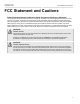

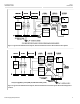
Table Of Contents
- RUGGEDCOM WIN7000
- Table of Contents
- FCC Statement and Cautions
- 1. Introduction
- 1.1. About this Guide
- 1.2. Capabilities and Features
- 1.3. Safety Information
- 1.3.1. General
- 1.3.2. Power Supply Requirements
- 1.3.3. Equipment Installation
- 1.3.4. Radio Frequency (RF) Exposure
- 1.3.5. Lightning Protection
- 1.3.6. Power Cord Protection
- 1.3.7. Servicing
- 1.3.8. Antenna Grounding Requirements
- 1.3.9. Outdoor Grounding System
- 1.3.10. User Ports and Power Supply
- 1.3.11. Safety Hazards
- 1.4. WIN7000 Physical Specifications
- 2. Site and Installation Requirements
- 3. Installation Procedures
- 3.1. Pre-Installation Safety Instructions
- 3.2. Package Components and Unpacking
- 3.3. Installation Tools
- 3.4. Installing the Base Station
- 3.5. Weatherproofing
- 3.6. Hazardous Location Information
- 3.7. Hazardous Location Installation
- 4. Setup
- 5. Troubleshooting
- Appendix A. Connector and Cable Pinouts
- Appendix B. WIN7000 Specifications
- Appendix C. List of Acronyms
- Appendix D. Warranty

Chapter 1
Introduction
RUGGEDCOM WIN7000
Installation Guide
2 Safety Information
• Backbone Ethernet connectivity via a 10/100 Base-T network interface
• Fixed and mobile CPE support
• 3.5 MHz, 5MHz, 7MHz and 10MHz channel bandwidth support
• MIMO (2×2) support
• Various Radio Frequency (RF) options, including 1.x, 2.x and 3.x GHz band support
• Traffic classification and connection establishment initiation
• Quality of Service (QoS) management
• Alarm management
• Internal SNMP agent, enabling extensive In-Band (IB) management of the base station and its registered CPEs
• R6 interface to ASN-GW profile C
• Power requirement: 48VDC
Section 1.3
Safety Information
Section 1.3.1
General
• Read this user manual and follow all operating and safety instructions.
• The base station and antenna must be installed by a professional installer.
• Do not exceed the described limits.
Section 1.3.2
Power Supply Requirements
• The power supply unit should be a Class 2 power supply, safety-certified according to national codes.
• Maximum output current should not exceed 5A.
• Maximum output voltage of the power supply should not exceed 60VDC.
• Minimum output voltage should not be below 42VDC.
• The disconnecting device is defined as the following:
▪ When connected to an AC/DC power supply, the appliance coupler of the AC/DC power supply is regarded
as the main disconnecting device for the base station.
▪ When connected to a DC battery power supply, a double pole circuit breaker, rated 10A 60VDC, is regarded
as the main disconnecting device for the base station.
The unit is considered to be connected to a centralized DC power system, therefore the power line should be
grounded. The unit should be permanently connected to ground with 16AWG cable or less. See the figures below
for two methods of power grounding (from the UL 60950-1 standard; according to UL 60950-22). When the unit is
connected to a centralized DC Power System, the "+" side of the supply should be grounded, as per UL60950-1
and UL 60950-22 requirements.