
Installation Manual


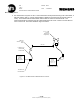

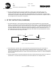
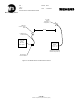
Table Of Contents
- SCOPE
- RELATED DOCUMENTS
- TERMINOLOGY
- INSTALLATION INSTRUCTIONS
- RF TEST INSTRUCTIONS (WAYSIDE)
- RF TEST INSTRUCTIONS (CARBORNE)
- ANNEX 1: GENRAL CONFIGURATION 1 – PARTS LIST
- ANNEX 2 – GENERAL CONFIGURATION 2 – PARTS LIST
- ANNEX 3A: GENERAL CONFIGURATION 3A– PARTS LIST
- ANNEX 3B: GENERAL CONFIGURATION 3B – PARTS LIST
- ANNEX 4A: GENERAL CONFIGURATION 4A – PARTS LIST
- ANNEX 4B: GENERAL CONFIGURATION 4B – PARTS LIST
- ANNEX 5A: GENERAL CONFIGURATION 5A – PARTS LIST
- ANNEX 5B: GENERAL CONFIGURATION 5B – PARTS LIST
- ANNEX A: ANTENNA CONFIGURATION A
- ANNEX B: ANTENNA CONFIGURATION B
- ANNEX C: ANTENNA CONFIGURATION C
- ANNEX D: ANTENNA CONFIGURATION D
- ANNEX TR: TEST RECORD

New York City Transit
Réf. : Ed/Rév :00/02
Trad.: --
Mémo : Date : 01/28/2003
DCS RF INSTALLATION INSTRUCTIONS
- 10 / 38 -
Siemens Transportation Systems exclusive property
Anritsu Site
Master
RF Power
Meter Option
Wayside Transmitter
Enclosure
For exact
configuration - See
Annex 5A - 5B
CRE placed in permanent
transmit mode (5 Sec TX)
1.5 Meter N to N
Coaxial Cable
RF Detector for
RF Power Meter
Figure 6.2 - RF Measurement of CRE w/Antenna at 50 Ft.
6 dBi Horn
Antenna - Astron
P2406
9 or 14 dBi
Antenna
(depends on
configuration)
50 Feet