
Installation Manual


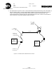

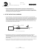
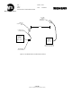
Table Of Contents
- SCOPE
- RELATED DOCUMENTS
- TERMINOLOGY
- INSTALLATION INSTRUCTIONS
- RF TEST INSTRUCTIONS (WAYSIDE)
- RF TEST INSTRUCTIONS (CARBORNE)
- ANNEX 1: GENRAL CONFIGURATION 1 – PARTS LIST
- ANNEX 2 – GENERAL CONFIGURATION 2 – PARTS LIST
- ANNEX 3A: GENERAL CONFIGURATION 3A– PARTS LIST
- ANNEX 3B: GENERAL CONFIGURATION 3B – PARTS LIST
- ANNEX 4A: GENERAL CONFIGURATION 4A – PARTS LIST
- ANNEX 4B: GENERAL CONFIGURATION 4B – PARTS LIST
- ANNEX 5A: GENERAL CONFIGURATION 5A – PARTS LIST
- ANNEX 5B: GENERAL CONFIGURATION 5B – PARTS LIST
- ANNEX A: ANTENNA CONFIGURATION A
- ANNEX B: ANTENNA CONFIGURATION B
- ANNEX C: ANTENNA CONFIGURATION C
- ANNEX D: ANTENNA CONFIGURATION D
- ANNEX TR: TEST RECORD

New York City Transit
Réf. : Ed/Rév :00/02
Trad.: --
Mémo : Date : 01/28/2003
DCS RF INSTALLATION INSTRUCTIONS
- 6 / 38 -
Siemens Transportation Systems exclusive property
WAYSIDE TRANSMITTER ENCLOSURE
For exact Configuration - See Annex 1 - 4B
Power
Splitter
B
A
C
Antenna 3
Antenna 4
Lighting Arrestor
to Radio
Lighting Arrestor to
Antenna
Figure 5-2 - Cable System Loss -
Quad Antenna Array
Power
Splitter
Antenna 1
Antenna 2
2. RF measurement of the radio. This test measures the RF output of each WRE. The WRE under this test
will be placed in continuous transmit mode (5 sec on/5 Sec off). Measurement will be accomplished using
the RF Power Meter Option of the Anritsu Site Mater 251C. This reading will be recorded in the WRE RF
Power Measurement Column of the Test Record Form in Annex TR. This value together with the
minimum specified path loss for any configuration and antenna gain will be used to determine compliance
with the RF output requirements. The configuration of this test is outlined in figure 5.2 below. The 1.5
meter test cable loss will be measured prior to testing and this loss will be added to the RF power output.
A n ritsu S ite M a s te r
RF Power Meter Option
W ayside Transm itter
Enclosure
For exact configuration -
See Annex 1 - 4B
W R E placed in perm anent
transm it m ode (5 Sec TX)
1.5 Meter SM A to
N Coaxial Cable
R F D e te c to r fo r
RF Power Meter
Figure 5.3 - R F M easurem ent of W RE