
Installation Manual


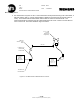

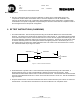
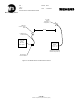
Table Of Contents
- SCOPE
- RELATED DOCUMENTS
- TERMINOLOGY
- INSTALLATION INSTRUCTIONS
- RF TEST INSTRUCTIONS (WAYSIDE)
- RF TEST INSTRUCTIONS (CARBORNE)
- ANNEX 1: GENRAL CONFIGURATION 1 – PARTS LIST
- ANNEX 2 – GENERAL CONFIGURATION 2 – PARTS LIST
- ANNEX 3A: GENERAL CONFIGURATION 3A– PARTS LIST
- ANNEX 3B: GENERAL CONFIGURATION 3B – PARTS LIST
- ANNEX 4A: GENERAL CONFIGURATION 4A – PARTS LIST
- ANNEX 4B: GENERAL CONFIGURATION 4B – PARTS LIST
- ANNEX 5A: GENERAL CONFIGURATION 5A – PARTS LIST
- ANNEX 5B: GENERAL CONFIGURATION 5B – PARTS LIST
- ANNEX A: ANTENNA CONFIGURATION A
- ANNEX B: ANTENNA CONFIGURATION B
- ANNEX C: ANTENNA CONFIGURATION C
- ANNEX D: ANTENNA CONFIGURATION D
- ANNEX TR: TEST RECORD

New York City Transit
Réf. : Ed/Rév :00/02
Trad.: --
Mémo : Date : 01/28/2003
DCS RF INSTALLATION INSTRUCTIONS
- 9 / 38 -
Siemens Transportation Systems exclusive property
6. After any maintenance activity involving a modification or change of the coaxial cable wiring or RF
components, all tests will be conducted in order to check the compliance of the RF installation. The
reference for all tests will be a RF configuration sheet established for each configuration. It indicates all RF
characteristics of a specific configuration, and particularly the reference values used for compliance check to
the FCC approval test for the specific configuration.
6. RF TEST INSTRUCTIONS (CARBORNE)
1. RF coaxial cable tests - this test will be performed using the Anritsu Site Master 251C Antenna & Cable
Analyzer. The Anritsu 251C will be used to measure power output at point “A”. This reading will be recorded
in the CRE Power Output column of the Test Record Form in Annex TR and, together with antenna gain, will
be used to determine compliance with the RF output power requirement. The Anritsu 251C will also be used
to measure reflected power in the cable system between the lightning arrestor to the antenna (“B” to “C”).
This reading will be recorded in the Cable Reflected Power Loss column of the Test Record Form in Annex
TR. These tests will be as per Figure 6.1 below:
CARBORNE TRANSMITTER ENCLOSURE
For exact Configuration - See Annex 5A - 5B
B
C
A
Antenna
SMA to N Coaxial
Cable to Radio
N to N Coaxial
Cable to Antenna
Figure 6-1 - Carborne Power Measurements
2. RF measurement of system at 50 ft. This measurement will be performed using a RF Power Meter, 6
dB Horn antenna, and a 1.5 meter coaxial cable at a distance of 50 feet from the antenna. These
measurements will be made with the CRE in continuous transmit mode. The measurements will be recorded
in the RF Power Measurement at 50-Ft. column in the Test Record Form in Annex TR. This test is detailed in
Figure 6.2 below.
3. RF power measurement of carborne transmission unit will be made at reference point A above in continuous
transmit mode. The value will be recorded in the Test Record Table for FCC compliance check.