0562p01 s TX-I/O™ Engineering and installation guide For Desigo V2.
Contents 1 Introduction ...................................................................................................5 1.1 Revision history .............................................................................................5 1.2 About this manual .........................................................................................5 1.3 Other applicable documents .........................................................................6 1.4 Before you start ......................
4.6.1 4.6.2 4.6.3 Procedure and label allocation ................................................................... 33 Labeling the I/O modules ............................................................................ 33 Addressing .................................................................................................. 34 5 Control panel .............................................................................................. 35 5.1 Control panel requirements ........................
9.4 9.4.1 9.4.2 9.4.3 9.4.4 Display ........................................................................................................63 Overview: indication per signal type / I/O function ......................................63 LED behavior ..............................................................................................64 General: LCD graphics ................................................................................65 Start-up and reset response ................................
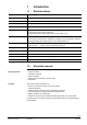
1 Introduction 1.1 Revision history May 2019 Revision _13 Power supply modules and BIMs: Internal fuse M 10A July2013 Revision _12 Voltage drop and cable lengths (sections 10.2, 10.4, 10.12, 10.13, 10.14, 10.15) Nov.2013 Revision _11 Triacs: voltage drop and cable lengths (sections 10.2, 10.13, 10.14) Feb.2013 Revision _10 Wiring of field devices in sections 6.3, 6.6, 10.12.3, 10.13 Nov.2012 Revision _09 Type designations in section 9.2 Mar.2012 Revision _08 Amendments concerning TXM1.
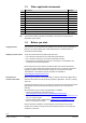
1.3 Other applicable documents [1] Document TX-I/O™ Range overview Number CM2N8170 [2] TX-I/O™ Module data sheets CM2N8172 ff [3] TX-I/O™ Power supply module / bus connection module data sheet CM2N8183 [4] TX-I/O™ Functions and operation CM110561 [5] P-bus bus interface module data sheet CM2N8180 [6] PROFINET BIM data sheet CM2N8186 [7] Replacement of legacy modules CM110563 [8] Island bus expansion module CM2N8184 [9] PROFINET BIM Operator's manual CM110564 [10] PXC3...
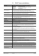
1.5 Term Bus master Island bus (TX-I/O module bus) Island bus expansion Power supply module Bus connection module Bus interface module (BIM) P-bus BIM PROFINET BIM I/O island Sub-island I/O row I/O module (assembly) I/O point Terminal Plug-in module Terminal base Address key Reset key I/O function Signal type TRA Addressing Local override, tool override, "functional test" etc. TX-I/O™ terms and definitions Description Device with supervisory function for an assigned set of I/O devices.
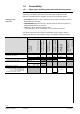
1.6 Compatibility 1.6.1 Signal types, building automation and control systems This document describes the full functionality of the TX-I/O module system. Depending on the building automation and control system not all functions are supported, especially when the integration is made via a bus interface module. Labeling in this document • P-Bus BIM designates functions / restrictions that are valid for integration via P-bus BIM (Desigo V2.37 and later).
Analog inputs Temperature Pt100 Ω (4-wire) Resistance 250 Ω (Pt 100) AI Pt100 4 Wire AI Pt100 (AI) (AI) Resistance 250 Ω AI 250 Ohm (AI) Temperature Pt 1000 (Europe) Temperature Pt 1000 (USA) Resistance 2500 Ω (Pt 1000) Temperature LG-Ni 1000, up to 180 °C Temperature LG-Ni 1000 Resistance 2500 Ω Temperature NTC 10 K Temperature NTC 100 K Temperature T1 (PTC) Voltage DC 0 .. 10V Current DC 4 .. 20 mA Current DC 0...
1.6.2 Topic Selection of functionality Integration of TX-I/O modules. Signal types Tools (For details, see [6], [9]) Download Addresses Resolution of the process values D20R C Pt100_4 P100 R250 Multistate inputs Multistate outputs Function test TX OPEN V2.37 Further functions V4 and later Simatic S7-300 / 400 Indirectly by selecting the automation station in XWP.
1.7 Where are the TX-I/O™ modules used? In hardware terms, a typical building automation and control system includes the following three areas: Area Management station (management level) Control panel (automation level, described in this document) Building services (field level) Brief description The management station is the workstation from which the operator manages and monitors all the building services plant in the building automation and control system.
2 Safety guidelines 2.1 Cyber security disclaimer Siemens provides a portfolio of products, solutions, systems and services that includes security functions that support the secure operation of plants, systems, machines and networks. In the field of Building Technologies, this includes building automation and control, fire safety, security management as well as physical security systems.
2.3 System-specific regulations Safety Electrical safety in the building automation and control systems supplied by Siemens Building Technologies is essentially based on the use of extra low voltage which is strictly segregated from the mains voltage.
Fuses to protect AC 24 V operating voltage Transformers, secondary winding: based on the effective load of all connected devices in accordance with the transformer sizing: • The AC 24 V conductor (system potential) must always be fused • Where specified, an additional fuse must be provided for the reference conductor ⊥ (system neutral).
2.4 Specific regulations for TX-I/O devices 2.4.1 Safety notes for engineering If you are responsible for the control-panel engineering, you should check that you have access to the documents listed in Section 1.3. Observe the engineering notes and safety regulations in these documents. 2.4.2 Electrical isolation Wiring safety notes Type Relay outputs I/O island Direct island bus integration (PXC3...) Direct island bus integration PXC100..., PXC200...
I/O modules The following regulations apply to the I/O modules: Item Combination of mains and low voltage is admissible Status contacts Regulations With relay modules the safe distance of PCB tracks and terminals is wide enough to make the combination of mains and low voltage on the same module permissible. • Digital inputs are not electrically isolated from the system electronics. – Mechanical contacts must be volt-free. – Electronic switches must comply with SELV or PELV standards.
Principles diagram: Connection of the field devices to the I/O modules Key A B C D E F 2.4.4 Power supply module I/O modules Field devices with SELV/PELV circuits only Field devices with mains voltage and SELV/PELV circuits Field devices with mains voltage circuits only Double or reinforced insulation to EN 60 630, test voltage AC 3750 V Connection of a PC (tool) to a P-bus BIM The USB interface of the P-Bus BIM incorporates a safety circuit to prevent the transfer of hazardous voltages to the PC.
Simple example (Desigo) 3 TX-I/O™ module system and accessories 3.1 The I/O modules in the control panel The diagram below is a schematic representation of the modules in the control panel, and shows how they are connected to the bus master and to the relevant internal and external elements.
3.2 Example: two I/O rows The TX-I/O™ module system The upper I/O row receives its power from a power supply module, the lower I/O row from a bus connection module.
3.3 The I/O modules 3.3.1 Construction The following is an exploded diagram showing a single I/O module and accessories, and, to the right, a drawing of the complete module assembly, snap-mounted on a standard rail.
The following standard mounting rails can be used with the I/O module system: • Top hat rails TH35-7.5 to EN60715 (35 x 7.5 mm) • Other top hat rails that meet the following requirements: – Material thickness on the edge max. 1 mm thick, min. 3 mm wide – Inner opening min. 25 mm 35 ± 0,3 35 (25) min. 25 27 ± 0,2 min. 6.5 1 ± 0.04 0 7.5 -0.4 Suitable standard mounting rails min. 3 3.3.2 10762M044 min. 6.5 1 ± 0.04 35 min.
3.3.3 Electrical characteristics • Please also note the safety guidelines in Section 2 • For detailed electrical data, please refer to the module data sheets • The following points are of particular note: Bus connectors The bus cables are described below in Section 3.4 "TXS1.12F10 power supply module and TXS1.EF10 bus connection module".
3.4 TXS1.12F10 power supply module and TXS1.EF10 bus connection module For details see data sheet N8183, [3]. Note The following information is also applicable to the power supply function of the TXB1.PBUS P-Bus interface module (BIM), see data sheet N8180, [5]. 3.4.
3.4.2 Electrical characteristics Please refer to the principles of electrical design, Section 10. Circuit principles (TXS1.12F10 power supply module) 3 24V~ 4 5 CS 6 PTC CS CS PTC PTC STOP Note! CS 1 8183A01_02 24V~ M 10A 2 For AC 24 V, the bus is interrupted to the left, the supply module can only supply the modules to the right with 24V~V. Circuit principles (TXS1.
3.5 Island bus expansion module TXA1.IBE See datasheet N8184 for more details [8] 3.5.1 Design Attachment slide for standard rails ON BM DIP switch for bus master (island bus, setting instructions see page 93)) BM LED "COM", displays island bus communication COM Bus connector right Bus connector left BT TXA1.
3.6 Accessories 3.6.1 Bus covers 10762J014 • The purpose of the bus covers is as follows: – to terminate an I/O row mechanically – to prevent accidental physical contact with the bus contacts. • The covers are suitable for both the left and right end of the TX-I/O devices. • Each power supply module and bus connection module comes with 3 bus covers (includes 1 spare). 3.6.2 Address key Address key • The module address is mechanically encoded in the address key.
3.6.3 Module labeling • The plug-in module has a removable transparent cover (the label holder) for insertion of a label. The label can be used to describe the function of each I/O point. • Pre-perforated A4 sheets of labels can be ordered under ASN TXA1.LA4. • Desigo: The labeling is carried out on a plant-specific basis, using the Siemens Building Technologies engineering system. Labels can also be created and printed by the control panel builder with the aid of the BIM Tool.
Relevant documents 4 TX-I/O™ mounting instructions 4.1 Before you start The following documents must be taken into account when installing equipment in the control panel: 1. 2. Check list: Essential information This engineering and installation guide It contains general rules and instructions for the mounting and layout of the I/O modules and other equipment in the control panel.
4.2 Structure or an I/O island An I/O island is composed of the I/O modules and of the following elements: • Desigo TRA: For each I/O island ONE automation station. • Island bus integration: For each I/O island ONE automation station and a power supply module. • Integration via P-Bus BIM: For each I/O island ONE bus interface module (BIM) with integrated power supply.
AS B C C C Key ON BM N1 N1 Room automation station or Automation station with island bus N2 Automation station with P-bus N3 Simatic S7 300 / 400 U4 P-Bus-BIM (Bus interface module) with built-in supply U5 PROFINET BIM U1 TXS1.12F10 power supply module U2 TXA1.IBE Island bus expansion module (optional) X1 TXS1.
4.4 Replacing a module Plug-in module A plug-in module can be replaced at any time by the same or a compatible type, even while the system is running. Module assembly When replacing a complete I/O module assembly, please note the following: • The bus connector extends from the right-hand side of all TX-I/O devices. For this reason, the adjacent plug-in module to the right must be unplugged from its terminal base.
4.5 Replacing a bus interface module If you replace a P-Bus BIM, it is mandatory that the new BIM contains no old IOMD. Otherwise the connected I/O modules are re-configured immediately after powering the BIM with AC 24 V or after connecting the I/O modules to the BIM. P-Bus BIM In order to fully reset a P-bus BIM, the following steps are required (see also Knowledge base entry KB 807): 1. 2. 3. 4. 5. 6. 7.
Different procedures 4.6 Labeling and addressing the modules 4.6.1 Procedure and label allocation Depending on the running of the project, and on how the flow of products is organized, the labels are – either supplied with the devices to be installed, – or inserted at the commissioning phase on the site where the plant is located 4.6.
4.6.3 Addressing • To enable the bus master to identify and communicate with a given I/O module, each I/O module requires its own address. • Without address key the module is in a secure, inactive state • With the address key inserted the module has its full functionality • The module address is mechanically encoded in the address key. This is plugged into the terminal base and swiveled into position in the I/O module.
Requirements 5 Control panel 5.1 Control panel requirements The table below contains information on the general control-panel requirements. Please use this table to check compliance with these requirements. Item Mechanical design Ambient conditions EMC compliant control panel Mechanical dimensions Requirements Check that the construction, stability and insulation of the control panel meet the regulations applicable to the location concerned.
5.2.2 Grouping and order of modules Criteria for the order of the I/O modules and the division into groups: • Internal / external – Outputs inside the control panel e.g. connections to starters for motor control – Outputs outside the control panel e.g. direct wiring to field devices such as sensors, transmitters, control equipment etc. • Arranged in ascending order of module address.
b >30 90 >30 b >30 10562z040 37/118 Siemens Building Technologies TX-I/O Engineering and installation guide Control panel CM110562en_13 2019-05-15
5.3 EMC compliant control panel Please refer also to Section 6.7, "EMC compliant wiring". Introduction One of the purposes of the control panel is to reduce electromagnetic interference. This depends on the internal and external electromagnetic interference (EMI) affecting the control panel. For example, an AC inverter in the same control panel may represent an internal source of interference, while external interference may be caused by a radio transmitter in the near vicinity.
6 Wiring 6.1 Before you start Before you start work on the wiring, please refer to Section 2, "Safety guidelines". More information is also available in Section 3.3.3, "Electrical characteristics of the TX-I/O modules". Notes • It is possible to start by mounting only the terminal bases. • However, the module assemblies can also be mounted as complete units (terminal base and plug-in module). The modules are inactive until the module power supply is connected to the bus.
6.3 Screw terminals Mechanical design The terminals used for the TX-I/O devices are rising-cage terminals. The wire is protected by a fixed contact plate between the wire end and the tip of the screw. Test pick-ups (test terminals) The I/O module terminals have test pickups (test terminals) for a pin diameter of 1.8 ... 2 mm.
6.4 Wiring of AC 24 V and bus Binding documents The control panel wiring must be carried out in compliance with the project-specific electrical diagram. Basic layout This example of a schematic diagram shows the basic connection of the power supply cables. Note Wiring example (Desigo) The wiring for the AC 230 V supply is not described specifically in this document. L N AC 230 V AC 24 V 24V~ T 24V~ 24V~ 24V~ 24V~ F1 ...
6.4.1 Cable materials Wiring for AC 24 V The requirements for the 24 V~ and ⊥ conductors of the AC 24 V supply are as follows: – Stranded or solid wire (copper) – Singly or in two-core cable Maximum cable lengths For details refer to Section 10.2. Separate transformer for each I/O island Recommendation: A separate transformer is recommended for each I/O island.
System ground (⊥) is connected in this case, since ⊥ serves as a common return. If a sub-island is powered by its own transformer, it may be earthed separately. If it is not earthed, an equalization wire must be installed. For earthing details and examples of the island bus expansion see section 10.6.6. Transformer phasing There is no need to take account of the relationship between the transformer phases. This means different phases (L1, L2, L3) can be used for the transformer supply.
6.4.3 Wiring island bus expansion Wiring material See Section 10.6 Maximum wire length See Section 10.6 Cabling the bus cable • Low-voltage wiring and cabled next wiring mains voltage, must have the same isolation strength as is used for the mains voltage. • We recommend separating low-voltage wiring from mains voltage for reasons of electro-magnetic compatibility. Recommended minimum distance: 150 mm.
6.5 Wiring examples 6.5.1 Principles AC 24 V is always connected in a "star" configuration (from terminal block K) For longer distances (typically between two control panels), the cables for bus and AC 24 V / ⊥ MUST be tied together. For shorter distances, also inside the control panel, we recommend this as well. Note Key Admissible cable lengths see Sections 10.4 and 10.5.
6.5.2 Example: 1 transformer, 1 or 2 control panels T K 10562z048 K 6.5.3 Example: 2 transformers, 1 or 2 control panels T T K 10562z049 K Note • System neutral of the two transformers must be connected as close as possible to the transformers. 6.5.4 Example: New power supply (module supply or AC 24 V) T1 10562z050 K Notes • A new provision is required in the following cases (for details refer to Section 10.3): – When the admissible supply current of 1.
6.5.5 Example: New supply (field supply V , AC/DC 12 … 24 V) T1 T2 K 10562z052 T3 Notes A new provision is required when a group of I/O modules requires a voltage different from AC 24 V for their field devices. Such a voltage (V ) can only be supplied by a bus connection module. The admissible range is AC / DC 12 ... 24 V, but the fuse LED only indicates 24 V. • The CS and CD.
6.6 Connecting the field devices Cable materials • 2-core cable without shield. • Single cores are not admissible, either inside or outside the control panel.
6.7 EMC compliant wiring Please refer also to Section 5.3 "EMC compliant control panel". Wiring rules In control panels or buildings where severe electromagnetic interference (EMI) is likely, devices susceptible to interference can be better protected by observing the following rules for wiring: Control panel wiring • Inside the control panel the connection terminals and cable trunking for unscreened conductors must be routed separately from screened conductors. • Avoid cable loops.
Notes • For more information, refer to Section 5.3 "EMC compliant control panel". • Special rules for connecting the screen apply in environments exposed to explosion hazards. Ethernet cables for PROFINET BIM Screened cables are compulsory! Fixing the cables in the control panel The cable screens of screened conductors must be connected to the metal structure of the control panel at the point of entry to the control panel, and to the equipotential bonding system of the building.
7 Introduction Checking activities • The following check lists apply to the fully installed control panel on the panel builder's site (not to the control panel on the customer site with all the external wiring). • The proposed sequence is intended as an aid to efficient working. 7.
7.2 Safety precautions and equipment specification Check that device protection and specifications comply with the regulations below: Ref. 1 2 3 4 Supply voltage 1 2 7.3 Addressing Item If the mains voltage is connected to the I/O modules (max.
7.4 Wiring test with unconfigured I/O modules See also Section 9.5 (diagnostics). The wiring test is best performed with unconfigured I/O modules (with DC 24 V supply present and address key swiveled inward – bus master not required). The default functions (factory-set I/O module status) have been specially designed for optimal testing. With configured modules, each I/O point would react differently according to the signal type.
7.5 Without bus master Other function checks If the modules are supplied with DC 24 V, the following operations can be performed with the local override facility of the modules (only outputs can be overridden): – if not configured: default function – if already configured: configured function if override permitted. With automation station • The functions of the I/O modules / field devices can be checked from the automation station.
8 Warning Removing and inserting modules without disconnecting the power Commissioning notes Before commissioning, the checks applicable to the I/O module system must be carried out as described in Section 7. This is particularly important in relation to checking for incorrect wiring which could put people or property at risk. See also Section 2, "Safety guidelines".
8.2 Response after reset Prerequisite The DC 24 V supply must be connected. Description The module responds as follows after inserting and swiveling the reset key inward: 1. All I/O status LEDs light up for approx. 1 s 2. After the reset, the modules behave as unconfigured modules (factory settings = default function for each I/O Point). Override settings due to local override are deleted. In which cases is a reset needed? • Replacement of a plug-in module by a previously used one (see 4.
9 Display, operation, and diagnostics 9.1 Indication and display of the I/O modules 20 V 21 19 28 V 24 V 23 25 29 27 31 33 Module status LED under the transparent address key (8) (7) (6) 12 (5) 32 V Override status LEDs (yellow) LCD display (1) (2) (3) (4) (5) (6) (7) (8) I/O status LEDs 2 4 V 3 (3) (2) 6 8 V 7 10 (4) 12 V 11 14 16 V 15 10762z054 (1) Module status LED • The module status LED (green) is located on the I/O module under the transparent address key.
V A Ni Display elements Configured signal type Signal value Errors, reminders Digital input, N/O contact • Open (inactive) • Closed (active) Above range limit Digital input, N/C contact • Closed (inactive) • Open (active) Below range limit Open circuit Step indicator for counter pulses Counter input Short circuit Pulse input, N/O contact Step indicator for switching pulses Pulse input, N/C contact 10561D206 10561D206 ? Examples Illegal action (local override) No current sensor (during wi
1) Insecure Output Signal – – Voltage outputs: the AC/DC supply for field devices is low or not available; therefore reliable operation of external devices cannot be guaranteed) Digital outputs (relays): the internal module operating power is low or not available; therefore reliable operation of the relay cannot be guaranteed 2) Insecure General – Voltage input signal types: the AC/DC supply for field devices is low or not available – Current inputs: the DC 24 V field supply is low.
9.2 Indication and display of the other island bus devices 9 9 RUN FLT IB PL DALI 1 2 8 10562z177 SRV PXC3... Room automation station with island bus connection 1 2 RUN 7 COM 7 COM FLT BAT INF 10562z153_02 SVC PXC....D Automation station with island bus connection 1 2 24V FLT 4 5 24V 24V 5 4 24V 24V 6 COM 10562z152_01 3 RUN TXA1.IBE Island bus expansion module P-Bus Interface- module (BIM) TXB1.PBUS Power supply module TXS1.12F10 Bus connection module TXS1.
Fuse LED for field supply (Bus connection module only) COM (yellow) ON OFF V (field supply voltage) input present (> 22 V), and Fuse OK Voltage <22Vare not indicated! No V (field supply voltage) input, or fuse blown Indicates island bus communication • Irregular flashing communication island bus • Brightly ON Reset / short circuit on island bus, all modules are inactive • Permanently OFF No supply /no communication / island bus expansion not wired IB (yellow) Island bus Indicates communication
9.3 Local override • The local override facility is available only on certain modules. In principle, plug-in I/O modules with and without a local LCD panel/operator controls are compatible and interchangeable. • Only outputs can be overwritten. Any attempt to overwrite an input results in an error indication. • Local override also operates without a bus master, provided that the DC 24 V module supply is present and the address key is plugged in.
9.4 Display 9.4.1 Overview: indication per signal type / I/O function LCD 0 ... 2500 Ω 0...250 Ω 0...2500 Ω 0...250 Ω OFF OFF variable variable Sensor type (no LCD) variable (no LCD) -50...
Pulse Briefly off Irregular • • • Cause LED flashing patterns (faults, information) (Fl_x = number of the flashing pattern) Pulse 10762z099 Fl_1 2s Fl_2 Dual pulse Flashing 0.5 Hz 2s Fl_4 Dual off pulse Fl_5 Rapid flashing 0.
9.4.3 General: LCD graphics • For a detailed description of normal operation, see above, page 58. • For diagnostics, see below. 9.4.4 Start-up and reset response See Section 8.
9.5 Diagnostics based on the LED indicators – (integration via island bus) Faults and information, based on the example of an I/O island with one automation station and two power supply modules (Supply 1 and 2) Autom. station RUN FAULT LED LED 3) Supply 1 AC24V DC24V LED LED 2) DISPLAY Supply 2 1) Modules 4) AC24 DC24V Module Other V LED LED status LEDs 1) 2) LED 2) FAULT / INFORMATION DETAILS DC24V from bus 2) A) Operation, configuration, communication etc.
Autom. station RUN FAULT LED LED 3) Supply 1 AC24V DC24V LED LED 2) DISPLAY Supply 2 1) Modules 4) AC24 DC24V Module Other V LED LED status LEDs 1) 2) LED 2) FAULT / INFORMATION DETAILS DC24V from bus 2) B) Power supply ON OFF ON ON ON ON ON Normal > 21.5V Normal operation ON ON ON ON ON ON ON ON ON ON ON ON Fl_3 OFF Normal OFF 16 … 20.5 Supply overloaded 2), 4) < 16 V An eventually defective supply in a power supply module is not recognized as long as DC 24 V > 21.
9.6 Diagnostics based on the LED indicators – Integration via P-Bus BIM Faults and information, based on the example of an I/O island with one P-Bus BIM and two power supply modules (Supply 1 and 2) RUN LED P-Bus BIM FAULT AC24V DC24V LED LED LED 3) 2) DISPLAY Supply 1 Supply 2 1) Modules 4) AC24V DC24V AC24V DC24V Module Other LED LED LED LED status LEDs 2) 1) 2) LED 2) FAULT / INFORMATION DETAILS DC24V from bus 2) A) Operation, configuration, communication etc.
RUN LED P-Bus BIM FAULT AC24V DC24V LED LED LED 3) 2) DISPLAY Supply 1 Supply 2 1) Modules 4) AC24V DC24V AC24V DC24V Module Other LED LED LED LED status LEDs 2) 1) 2) LED 2) FAULT / INFORMATION DETAILS DC24V from bus 2) ON OFF ON ON ON ON ON ON ON Normal > 21.5V Normal operation ON ON ON ON ON ON ON ON ON ON ON ON ON ON ON ON Fl_3 OFF Normal OFF 16 … 20.
9.
10 Principles of electrical design 10.1 Definitions Cable materials and cable routing: see Section 6.4 and 6.6. Wiring examples: see Section 6.4.2. From an electrical perspective a distinction can be made between the following elements: Island bus signal The island bus signal is based on the CD (Communication Data) , CS (Communication Supply) and system neutral (⊥) conductors.
Field device supply For field devices requiring a supply other than DC 24 V, the bus includes a separate conductor (24V~ / V ). The return is via ⊥ (system neutral). The admissible current is max. 6 A. This conductor can be supplied in one of two ways: – with AC 24 V from a bus interface module or a power supply module. This voltage is protected in the bus interface module / power supply module by a 10 A fine-wire fuse. – with AC / DC 12 … 24 V from a bus connection module.
10.
Admissible voltage, module supply DC 24 V 10562z165 In order to run correctly, the TX-I/O modules require a supply voltage (CS) above DC 21.5 V. This voltage can be measured on the terminals of a TXM1.8X module that lies in the I/O row most distant from the power supply. V Min 21.5 V Admissible voltage difference, module supply The module supply voltage CS must not deviate by more than 0.5 V between any 2 points of an I/O island (refer also to Section 6.4.2 "Wiring examples").
10.3 Admissible number of devices Module power supply TXS1.12F10 or TXB1.PBUS or PXC3... • Parallel operation: max. 4 power supply units per I/O island. • Parallel operation: max. 2 power supply units per I/O row Reason: max. current in the I/O row in case of a short-circuit. • Island bus expansion: for each decentralized sub-island again up to 4 parallel power supply modules, with up to 2 for each I/O row. Module power supply 3rd-party device DC 24 V An external power supply is connected via a TXS1.
10.4 Cables for AC 24 V This section concerns the cables between transformer and power supply inlet (BIM, power supply module, bus connection module, see Section 6.4). Installation example: Desigo L N AC 230 V AC 24 V 24V~ T 24V~ 24V~ 24V~ 24V~ F1 ...A K F2 N1 U1 AC 24 V F3 Island bus U1 10762z151 X1 F4 Calculation basis AC 24 V is always connected in a star configuration (see the wiring examples 6.4.1). The calculations are based on the voltage drop value (0.
Power consumption The power consumption of the devices is as follows: Device Power consumption (individual items) Without module and field device load Island bus at maximum admissible load DC 24 V / 1.2 A Island bus at maximum admissible load DC 24 V / 0.
10.5 Cables for the island bus (DC 24 V) A critical factor when planning the layout of remote sub-islands is the admissible length of the island bus cables. In the case of the AC 24 V supply voltage, long distances are easy to overcome by ensuring that the sub-island has its own transformer (see the wiring diagrams in Section 6.5). With the island bus, however, the cable length is limited by capacitance and by voltage drop. • The total capacitance of all cable sections in an I/O island must not exceed 4.
Cable material • Two- or three-core round cable, insulated for 300 V or higher (control cables, sensor cables, power cables, field bus cables, etc.) Examples: Harmonized cable in accordance with CENELEC HD 361 52: H05VV-F (stranded) or H05VV-U (solid wire). Round cables MUST NOT be wired in parallel as a means of increasing the crosssection. Otherwise the capacitance between CS and CD would increase.
AC 24 V T2 CD CS 10562z137 10562z136 T1 CS T T (Earthing: see Section 6.4, 6.4.
10.5.1 Max. cable lengths for island bus Capacitance of two-core cables depends on the following (with decreasing importance) – Material (dielectrical constant εr), the lower the better, values below 4.5 are OK – Insulation thickness b (the thicker the better) – conductor's diameter a (the thinner the better) dielectrical constant values Material Max. cable lengths Cable type PVC Polyethylene Silicon TPE (PETP) Teflon Nylon a b 10562z116 Estimation of capacitance εr 4 ... 4.5 2.4 3.2 3.3 2.1 3.
10.5.2 Installation rules for island bus T A T B T Glossary for the Topologies T TXS1.12F10 C 10562z119 V4: AS + Supply V2.37: TXB1.P-BUS TXS1.12F10 T D TXS1.EF10 Key Rules concerning the topology TXS1.EF10 E TXS1.EF10 A I/O island, consisting of sub-islands B and C. B Local sub-island with a local I/O row D. C Remote sub-island with remote I/O rows E.
10.5.2.1 Examples without any remote supplies < 0.6A A < Lmax < 0.4A < 0.4A B < 1/2 Lmax < Lmax < 0.3A C < 0.3A < 0.3A < 1/3 Lmax < 2/3 Lmax < Lmax < 0.2A < 0.2A D < 0.2A < 0.2A < 0.2A < 1/5 Lmax < 2/5 Lmax < 3/5 Lmax < Lmax Notes 10562z130a < 4/5 Lmax • The sum of all island bus cable segments must not exceed Lmax (see 10.5.1).
F < 0.6A < 0.6A < Lmax < Lmax < 0.4A < 0.4A < 0.6A G < Lmax < 1/2 Lmax < Lmax < 0.4A < 0.3A < 0.4A < 0.3A < 0.3A H < 1/2 Lmax < 1/3 Lmax < 2/3 Lmax < Lmax < 0.6A I L3 < Lmax < 0.6A L1 < Lmax L2 < Lmax 105 62 z13 1a_ 01 < 0.6A L1 + L2 + L3 < Lmax Notes • If high currents are required in the remote I/O rows, the supply should be placed in the "center" of the sub-island. • If the total current exceeds 1.2 A, a multiple supply is required (see10.5.2.4).
10.5.2.2 Examples with 2 remote supplies (2 sub-islands) K ~0 A < 1.2 A < 1.2 A < 1.2 A < 1.2 A < 1/4 Lmax < 1/4 Lmax < 1/2 Lmax < 1/2 Lmax < Lmax L L3 L7 < 1/4 Lmax < 1/4 Lmax < 1/2 Lmax < 1/2 Lmax < 1.2 A < 1.2 A L4 ~0 A L2 L5 < 1.2 A < 1.2 A < 1.2 A < 1/4 Lmax L6 < 1.2 A < 1/4 Lmax < 1/2 Lmax < 1/2 Lmax 10562z133a L1 L1 + L2 + ... + L7 < Lmax Notes • The sum of all island bus cable segments must not exceed Lmax (see 10.5.1).
Examples with 4 remote supplies 10562z142a 10.5.2.3 M < 1.2 A < 1.2 A < 1.2 A ~0 A ~0 A ~0 A < 1.2 A < 1.2 A < 1.2 A < 1.2 A <1/4 Lmax < 1.2 A <1/4 Lmax < 1/2 Lmax < 1/2 Lmax < 1/2 Lmax < 1/2 Lmax < Lmax N ~0 A < 1.2 A < 1.2 A <1/4 Lmax < 1/2 Lmax < 1/2 Lmax L2 L1 L3 ~0 A < 1.2 A < 1.2 A < 1.2 A < 1.2 A < 1.2 A <1/4 Lmax < 1.
10.5.2.4 Multiple supplies Recommended V2.37: TXB1.P-BUS V4: AS + Supply TXS1.EF10 TXS1.12F10 10562z111 If currents higher than 1.2 A must flow out of an I/O row, a multiple supply is required. If two or more supplies together deliver current to an I/O row other than their own (be it local or remote), these supplies must themselves be placed in different I/O rows. They must be connected by a short cable via the screw terminals. I > 1.2 A V2.37: TXB1.P-BUS V4: AS + Supply TXS1.12F10 TXS1.
10.6 Island bus expansion 10.6.1 Benefits of island bus expansion • The island bus expansion modules allow for “decentralized” sub-islands with TX-I/Omodules, that may be located up to 2 x 200 m from the "local" sub-island. • The island bus expansion is based on differential RS-485 transmission technology. • Programming / parameterization not required. • The DIP switches for the bus master and bus terminator must be set correctly on the island bus expansion modules.
10.6.4 Island bus expansion cable material Cable specifications for island bus expansion Cable types The cables must meet the following specifications: • • • • Shielded cable (foil or mesh) Capacitance between wires + and – Wave resistance between wires + and Specific resistance for wires + and – – <50 pF/m 100...120 Ohm <100 Ohm/km (AWG24 or thicker) The following cable types normally suit the requirements for island bus expansion.
Wiring CAT 5-6-7 RS485 (4 strands) RS485 (2 strands) + _ S PELV and SELV are admissible _ + 10562z162 10562z166 10562z167 N.C. PELV and SELV are admissible S= screen connection (optional) on both ends as described on page 50 N.C.
10.6.5 Installation rules for island bus expansion Glossary on topology T F B G T G D TXS1.EF10 TXS1.EF10 T T T T TXS1.12F10 G F TXS1.12F10 TXA1.IBE Bus Master + Supply TXA1.IBE TXS1.EF10 C TXS1.12F10 TXS1.EF10 E T E TXS1.EF10 10562z145_01 TXS1.EF10 T T TXS1.12F10 TXA1.IBE T T T A Key A I/O island, consisting of a local sub-island B, a remote sub-island C as well as two decentralized sub-islands F. B Local sub-island with local I/O row D.
Earthing rules For earthing rules, refer to section 6.4.1, for wiring examples refer to section 10.6.6 Topology rules 13. 14. 15. 17. 18. Maximum wire lengths for island bus expansion 19. 20. The admissible length of the island bus expansion is 400 m. The maximum distance between the local sub-island (B) and the most distant decentralized sub-island (F) must not exceed 200 m.
Bus master, bus connection rules The island bus expansion module has DIP switches to set the functions "bus master" and "bus terminator". Communication can be interrupted when the switches are incorrectly set; there are no obvious symptoms, however, when a switch is incorrectly set. 24. 25. When both BM switches are on, the island bus expansion modules serves as the island bus master. This is required for decentralized sub-islands. The automation station or the BIM is the master for local sub-island.
10.6.6 Wiring examples for island bus expansion Wiring of the island bus expansion can be executed in different ways, depending on – the earthing kind of the system (PELV, SELV) – the cables used (Cat 5, RS-485, RG-62). Admissible cable types are described in 10.6.4. Admissible cable lengths see above, rule 19. When choosing a protection system (PELV, SELV), local safety regulations must be observed. A simple and effective installation is achieved with PELV earthing and CAT 5 (AWG24) cable.
T Connect the cable screen directly to the equipotential terminals expansion modules on both ends. T T T PELV CAT 5 or RS485 (4 conductors) 10562z170 T of the island bus T 10562z171 T T PELV RS485 (2 conductors) T T T PELV RG-62 T 10562z172 The equipotential bonding between the island bus expansion modules is done via a pair of conductors in the bus cable, connected in parallel. RG-62 cables of an existing remote P-bus installation can be re-used when migrating to TX or PX.
10562z173 T T 10562z174 T T T T SELV CAT 5 or RS485 (4 conductors) T T SELV RS485 (2 conductors) Connect the bus cable as in a PELV system. Additionally, system neutral of the two transformers must be connected by a separate cable. Tie the bus cable and the system neutral cable together to avoid loops (inductive disturbance).
10.6.7 Installation examples for island bus expansion STOP • In the installation examples, the island bus length is the same on both side of the island bus expansion (1/2 Lmax). Concerning Lmax, please refer to page 81. • Permissible power changes when other lengths are selected (see rule 21). Note! < 1.2A P < 200 m < 1/2 Lmax < 1.2A < 1/2 Lmax < 1.2A Q < 200 m < 1/2 Lmax < 1.2A < 200 m < 200 m < 1/2 Lmax < 1.2A < 200 m < 1/2 Lmax 10562z154 < 1.
< 1.2A < 1.2A < 1.2A < 1.2A < 1.2A < 1.2A < 200 m < 200 m R < 1/2 Lmax S ~0 A < 1.2 A < 1.2 A < 1.2 A < 1/4 Lmax < 1/2 Lmax < 1/2 Lmax < 1/2 Lmax 10562z155 < 200 m < 1.2 A < 200 m < 200 m < 200 m < 200 m < 200 m < 1/4 Lmax Notes • Example R illustrates 2 segments for the island bus expansion up to a maximum each of 200 m.
Solutions for sub-islands without power supply modules STOP In these examples earthing is not admetted because conductor ⊥ carries supply currents. Case 2 B. Note! First, for comparison purposes, example A without island bus expansion. The following lengths and power are permitted per page 81: < 0.6A 10562z156 A < Lmax Cable island bus (wire CS, CD and ⊥) Round cable 2.5 mm2 / AWG14 Coaxial cable parallel with 2.5 mm2 Length Lmax Max. power for remote I/O row 50 m 100 m 0.6 A 0.
10.7 Cables for field devices See below, Sections 10.11 ff. 10.
*) STOP Note! *) The DC 24 V consumption (from the modules) by field devices other than current sensors must be counted separately. Admissible current for each TXM1.8X, TXM1.8X-ML module: 200 mA (see Section 10.2). 10.9 AC 24 V transformer sizing The engineering responsibility includes transformer sizing. The selected transformer rating is based on the total power consumption of the automation station, the I/O modules and the connected field devices.
10.10 Fuses The engineering responsibility includes sizing of fuses. Item Fuses to protect the AC 24 V operating voltage Important AC 230 V mains voltage protection Regulations Transformer secondary winding: based on the effective load of all connected devices as determined by the transformer sizing: • AC 24 V (system potential) must always be fused. • Where specified, an additional fuse must be provided for the reference conductor ⊥ (system neutral).
10.11 Digital inputs (status and counting) Cable length STOP Counter inputs Common ⊥ conductor with multiple contacts Connection diagram (Example) The permissible length of the cables connected to the status contacts and counter contacts, regardless of the thickness of the wire (min. diameter 0.6 mm) is restricted to 300 m and is defined by the anticipated noise interference. Counter inputs faster than 1 Hz that are routed for more than 10 m in the same trunking as analog inputs must be shielded.
10.12 Analog inputs 10.12.1 Passive resistance sensors and resistance transmitters (2-wire connection) Measured value acquisition and measured signal The temperature sensors register the temperature by means of a nickel or platinum wire or a semiconductor which change their resistance in relation to the temperature. Key: R Sensor signal (resistance) T Actual temperature Resistance table The table below shows the resistance of the supported sensor elements as a function of the temperature.
Cable length The maximum permissible cable length for passive resistance sensors and transmitters depends on the permissible measuring error due to the line resistance (see the graphs below). The maximum cable length is 300 m.
Measured value error LG-Ni 1000 b) Measured value error due to explosion protection devices Overvoltage protection devices can falsify the measured value of analog inputs. Example: Phoenix type PT 1X2-12DC-ST/28 56 02 9 has an internal protective impedance which causes a measuring error of +1K, but only for LG-Ni 1000 sensors.
Measured value error NTC sensor Measured value error of NTC sensors due to line resistance: The sensors are highly non-linear. But thanks to the high sensor resistance the errors are very small. Error compared to T1: 20°C 100°C NTC 100K x 0.01 x 0.1 NTC10K x 0.
10.12.2 Correcting the line resistance with [Icpt] For analog inputs (measuring of temperature or resistance), most signal types are calibrated for a line resistance of 1 Ohm. Desigo: If the line resistance differs significantly from 1 Ohm, [Icpt] can be changed in the AI block. PROFINET BIM: The line resistance can be configured in the S7 HW Config Tool using parameter "Compensation". Resistance measuring Line resistance [Slpe] [Icpt] Delta Slope Delta Intercept AI PT1K385 (Europe) 0 Ohm 0.
Temperature measuring [1/100 °C] Line resistance [Slpe] AI PT1K385 (Europe) 0 Ohm Default = 1 Ohm 2 Ohm 3 Ohm 0.01 0.01 0.01 0.01 [Icpt] degrees per Ohm 0.259740 3.75 0.266667 5 0.2 9.57 10.39 11.31 12.36 0.104450 0.096246 0.088417 0.080893 0.259740 0 -0.259740 -0.519481 AI PT1K375 (USA) 0 Ohm Default = 1 Ohm 2 Ohm 3 Ohm 0.01 0.01 0.01 0.01 0.266667 0 -0.266667 -0.533333 AI Ni1000 extended 0 Ohm Default = 1 Ohm 2 Ohm 3 Ohm 0.01 0.01 0.01 0.01 0.2 0 -0.2 -0.4 0.01 0.01 0.01 0.01 0.
10.12.3 Active sensors DC 0 … 10 V Measured value acquisition and measured signal The active sensors use a signal amplifier which emits a standard DC 0...10 V signal. This voltage range is proportional to the application range of the sensor. A suitable measuring system is used to acquire the measured value.
Cable length for devices with AC 24 V The maximum cable length is 300 m / 1000 ft (DXR2: 80 m / 260 ft). The permissible length of the cables is calculated as follows: Voltage drop of max. 7 % (1.68 V) on the AC 24 V operating voltage for the sensor / actuator. Cable cross section Power 2.50 mm2 / AWG14 1.50 mm2 / AWG16 1.00 mm2 / AWG18 0.
10.12.5 Technical data for the analog inputs Compensation of the line resistance 1 Ohm, calibrated in the module, (except for Pt100_4, P100, NTC10K and NTC100K) Signaltyp Range (Under / over range) 5) Resolution island bus 3) Resolution P-Bus-BIM 3) Resolution PROFINET BIM 3) Temperature AI Pt100 4 Wire -50...400 (600) °C 1) 2) (-52.5...610°C) 20 mK 86 mK Resistance AI Pt100 0...250 Ohm (0...265 Ohm) 0...250 Ohm (0...265 Ohm) -50…150 (180) °C (-52.5 ...185.0 °C) -50...400 (600) °C (-52.5...
Caution! "Reduced hum injection" 4) The range monitoring of signal type U10 is done with a short NEGATIVE signal of –3,1 V, 0.05 mA (open circuit detection). If a field device has an open output, a negative voltage could appear there. This can damage any polarized components (e.g. capacitors). 5) When the process value is outside the range, a fault message is issued. 6) AI PT1K375: Restriction for hum injection only for TXM1.8P. No restriction for TXM1.8U und TXM1.8X. Signal type Normal hum TXM1.
10.13 Wiring for Triac outputs AC 24 V The following applies for wiring to actuating devices such as valves, damper actuators or protection connected to the Triac outputs: Cable material • Use stranded, 2 or multiple core round cables, screened (standard off-the-shelf installation cable). • Single wires may not be used. Cable laying • Wiring may be laid together with power lines (AC 230 V). They must be isolated from the power lines per regulations. Isolation must meet PELV requirements.
10.14 Wiring for Relay outputs • External fuse of max. T 10 A for protection of the PCB tracks. • The maximum load of the relay contracts must be observed (see data sheets for the corresponding devices). It may require a fusing <10 A. • Relays have volt-free relay contacts. The mains voltage / switching voltage (AC 230 V / AC/DC 24 V) must be supplied as an external voltage to the terminals. • The sizing and fusing of the lines are oriented to overall load and local regulations.
10.15 Analog outputs Outputs DC 0…10 V The permissible lengths of the cables between the control outputs and the modulating actuators depend on the type of actuator in use and are calculated as follows: – A voltage drop of max. 7 % (1.68 V) in the AC 24 V operating voltage for the actuator Reason: to ensure sufficient operating voltage for the actuator. – A control signal error of max. 1% of the positioning range, due to line resistance in the signal conductor.
Technical data for analog outputs Signal type Output voltage AO 0-10V Output current Output current 1) AO 4-20mA Output voltage Load resistance Range (under / over range) 0 … 10 V (-0.05...10.6 V) max. 1 mA Resolution Island bus 1 mV Resolution P-Bus BIM 11 mV Resolution PROFINET BIM 1 mV 4 ... 20 mA (3.92...20.96 mA) ca. DC 15 V 0 ... 500 Ohm 1 µA 1.7 µA 1 µA 1) TXM1.8X and TYM1.8X-ML only, and I/O points 5 ...
11 Disposal The devices and accessories in the TX-I/O ™ range described in this document are manufactured using environment-compatible materials and processes, and optimized to consume as little energy as possible. The device is considered electrical and electronic equipment for disposal in terms of the applicable European Directive and may not be disposed of as domestic garbage. • Dispose of the device through channels provided for this purpose.