
User Manual


10/118
Siemens TX-I/O Engineering and installation guide CM110562en_13
Building Technologies Introduction 2019-05-15
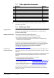
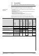
1.6.2 Further functions
Topic
V2.37
V4 and later
Simatic S7-300 / 400
Selection of
functionality
Indirectly by selecting the automation station in XWP. A "new",
island-bus capable automation station leads to other menus,
where the V4 signal types and the corresponding parameters can
be set.
Selected in S7 HW Config Tool
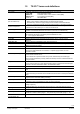
Integration of
TX-I/O modules.
Via P-bus interface module
(BIM)
Automation station directly
supports the island bus
Via PROFINET BIM
Signal types
V4 supports additional signal types
(See 1.6.1).
See 1.6.1
Tools
(For details,
see [6], [9])
The BIM tool generates the
IOMD.
The tool is now called the
BIM Tool under V4.
Configuration takes place
– In the Point Configurator
– In the I/O Address Editor (in the
CFC)
And is saved as an IOC.
Configuration is done in S7
HW Config Tool and saved in
S7 project
Download
The TX-I/O Tool loads the
module configuration (IOMD)
to the BIM (via USB).
For BIM integration under V4
(XWP) this tool is called BIM
Tool
Module configuration (IOC) is
loaded to the automation stations
with the CFC program.
Or directly to the module using
Desigo Point Test Tool via
BACnet.
Is done in S7 HW Config when
loading the S7 CPU
Addresses
The P-bus address (P=...)
includes the parameters
such as signal type, pulse
length, etc.
The island bus address (T=...)
does not include parameters,
these are in the IOC.
A signal type may occupy multiple
addresses (e.g. multistate).
The island bus addresses are
defined by address keys.
S7 addresses and parameters
are assigned to I/O channels in
the S2 HW Config
Resolution of the
process values
Resolution limited by the P-
bus specification
(nevertheless, better to some
extent than for PTM-I/O)
Direct island bus integration allows
for a higher resolution
Equal to island bus resolution
D20R
Signal types D20 and D20R
may be selected
Only signal type D20 may be
selected.
The function D20R must be
realized with Polarity in the I/O
Address Editor (CFC).
Signal types D20 and D20R
may be selected
C
Meter only up to 25 Hz
Select among
– Mechanical meter (up to 25 Hz)
– Electronic meter (up to 100 Hz)
– Meter function: Meter is reset at power down
Measure function: Meter state is stored at power down
Meter value storage only up
to 64; serves to bridge the
AS poll cycle.
Meter value storage up to (2
32
)–1 (≈4.3 x 10
9
)
Pt100_4
P100
R250
Not supported.
BIM integration under V4
supports P100 4-wire as well
as 250 Ohm 2-wire, but with
jumpers connected to 4
terminals such as PTM-I/O.
See datasheet N8176 for
connection diagram.
Pt100_4 and P100 are connected
with 4 wires, R250 with 2 wires.
Supports Pt100_4 with 4-wire
connection and R250 with 2-
wire connection
Multistate inputs
Are formed via a FW block and are compiled from multiple, individual I/O points
Multistate outputs
Supports only Q-M3 and
Q250-P3.
Other types must be
implemented via individual
I/O points in the MO block.
(Caution, the associated
I/O points can be indivi-
dually operated, both lo-
cally on the module and
using the tool!)
The island bus knows native MOs.
The associated I/O points cannot
be individually operated locally,
they are locked against one
another.
S7 supports Q-M1...Q-M4 and
Q250-P1...P4.
The PROFINET BIM operates
the MOs via individual S7
binary outputs.
The associated I/O points
cannot be individually
operated locally, they are
locked against one another.
Function test
Function test in the TX-IO
Tool
Various possibilities, see
CM110561
Test using the S7 Control /
Status Variable tool
TX OPEN
Not supported
See separate documentation
Not supported