
Data Sheet for Product


Technical Instructions 599 Series 2-Way Ball Valves
Document Number 155-703P25
May 28, 2020
Page 10 Siemens Industry, Inc.
Operation
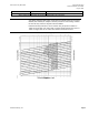
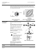
The parabolic shape of the flow characterizer orifice (Figure 2) provides a slowly
opening valve. Equal movements of the valve stem, at any point of the flow range,
change the existing flow an equal percentage regardless of the existing flow. The ball
valve equal percentage flow characteristic (Figure 3) mirrors the flow characteristic of a
coil, resulting in linear heat transfer.
Figure 2. Ball Valve Flow
Characterizer.
Figure 3. Ball Valve Equal Percentage
Flow Control.
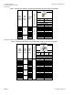
Mounting and
Installation
Install the valve so that the flow follows the
direction of the arrow cast on the valve
body.
For added flexibility, the actuator mounting
plate can be installed in any of the four (4)
rotation angles relative to the valve body.
For best performance, install the valve
assembly with the actuator above the
valve body.
The valve and actuator assembly can be
installed in a horizontal pipe in any position
between vertical and 90°.
The ball valve also can be installed
vertically.
CAUTION:
Do not install the valve assembly
so that the actuator is below
horizontal or upside-down.
See Ball Valve Bracket Kit
Installation Instructions 129-496
for complete and proper
installation and mounting
instructions.
Allow sufficient space for servicing the
valve and actuator. See Figure 6 and
Table 14 for valve body dimensions and
service envelope.
Figure 4. Mounting Positions.
Service
Replace the valve or actuator if inoperable.