
Install Instructions


Document No. 129-504
Installation Instructions
January 21, 2013
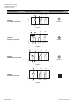
Auxiliary Switches
Switch
Switch
Makes
Switch
Breaks
A (fixed 5°) < 5° > 5°
B (fixed 85°) > 85° < 85°
NOTE: Both sets of contacts are open when the actuator
is between 5° and 85°. Switches may be wired in
a Normally Closed or Normally Open position.
SWITCH
A
SWITCH
B
DUAL AUXILIARY
SWITCHES
S1
S4
S2 S3 S5 S6
EA1293R1
N.C. N.O. N.C. N.O.
COMMON COMMON
CAUTION:
Mixed switch operation to the switching outputs
of both dual end switches (5° and 85°) is not
permitted.
Either AC line voltage from the same phase
must be applied to all four outputs of the fixed
dual end switches, or UL-Class 2 voltage must
be applied to all four outputs.
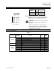
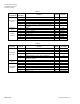
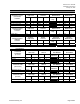
Wiring Terminations
Table 1.
Connecting
Standard
Symbol
Function Color
Color
Symbol
1 Supply (SP) Red RD
2 System Neutral Black BK
6 Control signal clockwise Violet VT
7 Control signal counterclockwise Orange OG
8 Input Signal: 2 to 10 Vdc or 10 to 2 Vdc (GQD15x) Gray GY
24 Vac/dc
Actuator
9 Position Output: 2 to 10 Vdc or 10 to 2 Vdc (GQD15x) Pink PK
3 Supply Black BK
120 Vac
4 Neutral White WH
1
Switch A − Common
Q11 Gray/red
2
Switch A − N.C.
Q12 Gray/blue
3
Switch A − N.O.
Q14 Gray/pink
4
Switch B − Common
Q21 Black/red
5
Switch B − N.C.
Q22 Black/blue
Auxiliary
Switches
6
Switch B − N.O.
Q24 Black/pink
Siemens Industry, Inc. Page 5 of 9