Technical Instructions Document No. 155-188P25 EA GDE/GLB-2 May 22, 2014 OpenAir™ Electric Damper Actuator GDE/GLB Series Non-spring Return, 24 Vac Floating Control, Rotary Description OpenAir non-spring return, 24 Vac, floating control, direct-coupled, actuators is designed for rotary electric dampers.
Technical Instructions Document No. 155-188P25 May 22, 2014 OpenAir™ Non-Spring Return, 24 Vac, Floating Control, Rotary Electric Damper Actuator Power supply Operating voltage (G–Y1 or G–Y2) Frequency Power consumption 24 Vac +20%, -15% 50/60 Hz 2.3 VA Equipment rating Rating Class 2 according to UL, CSA Class III per EN60730 Auxiliary features Feedback potentiometer (GDE/GLB132.
OpenAir™ Non-Spring Return, 24 Vac, Floating Control, Rotary, Electric Damper Actuator Technical Instructions Document No. 155-188P25 May 22, 2014 Specifications, Continued Ambient conditions Ambient temperature operation storage and transport Ambient humidity (non-condensing) -25°F to 130°F (-32°C to 55°C) -40°F to 158°F (-40°C to 70°C) 95% rh UL listed to UL873 cUL certified to Canadian Standard C22.2 No.
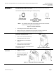
Technical Instructions Document No. 155-188P25 May 22, 2014 OpenAir™ Non-Spring Return, 24 Vac, Floating Control, Rotary Electric Damper Actuator Accessories, Continued Figure 5. Shaft Insert. ASK78.3U: Shaft insert for use with 3/8-inch (8 to 10 mm) diameter shafts. (Included in box with GDE/GLB Series). (Pkg/10) NOTE: Factory-installed 1/2-inch guide must be removed prior to installation. 985-101P25: Shaft guide insert, 1/2-inch 25 Pk (Factory-installed with GDE/GLB Series). Figure 6.
OpenAir™ Non-Spring Return, 24 Vac, Floating Control, Rotary, Electric Damper Actuator Technical Instructions Document No. 155-188P25 May 22, 2014 Legend Actuator Components 1. Base plate 2. Positioning scale for angle of rotation 3. Connection cables 4. Connection cables 5. Manual override 6. Coupling bushing 7. Factory installed 1/2-inch guide 8. Auxiliary switch A 9. Auxiliary switch B 10. Position indicator 11. Adjustment lever with locking screw (4 mm hex) Figure 11. Parts of the Actuator. 12.
Technical Instructions Document No. 155-188P25 May 22, 2014 OpenAir™ Non-Spring Return, 24 Vac, Floating Control, Rotary Electric Damper Actuator A floating control signal controls the damper actuator. The actuator’s angle of rotation is proportional to the length of time the signal is applied. A 24 Vac control signal to wires 1 and 6 (G-Y1) causes the actuator coupling to rotate clockwise. A 24 Vac control signal to wires 1 and 7 (G-Y2) causes the actuator coupling to rotate counterclockwise.
OpenAir™ Non-Spring Return, 24 Vac, Floating Control, Rotary, Electric Damper Actuator Mounting and Installation Technical Instructions Document No. 155-188P25 May 22, 2014 You must place the actuator on the damper shaft so that the front of the actuator is accessible. The label is on the front side. The minimum damper drive shaft length is 3/4-inch (20 mm).
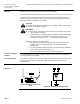
Technical Instructions Document No. 155-188P25 May 22, 2014 Wiring OpenAir™ Non-Spring Return, 24 Vac, Floating Control, Rotary Electric Damper Actuator All wiring must conform to NEC and local codes and regulations. Use earth ground isolating step-down Class 2 transformers. Do not use autotransformers. The sum of the VA ratings of all actuators and all other components powered by one transformer must not exceed the rating of the transformer.
OpenAir™ Non-Spring Return, 24 Vac, Floating Control, Rotary, Electric Damper Actuator Technical Instructions Document No. 155-188P25 May 22, 2014 Wiring , Continued Strain Relief Securing the wires/cabling will prevent breakage and ensure strong signals to the GDE131.1T model. The following is recommended: 1. The open bracket to the right of the actuator terminal strip is the strain relief for the customer provided control wires. 2.
Technical Instructions Document No. 155-188P25 May 22, 2014 OpenAir™ Non-Spring Return, 24 Vac, Floating Control, Rotary Electric Damper Actuator Wiring, Continued Post Header AMP, Continued GDE131.1N T T Daisy Chain The input cable (purchased separately) brings power and a control signal to the first actuator in a daisy chain configuration. Table 3.
OpenAir™ Non-Spring Return, 24 Vac, Floating Control, Rotary, Electric Damper Actuator Wiring, Continued Technical Instructions Document No. 155-188P25 May 22, 2014 Table 4. Daisy Chain Cable GDE131.1N 12 ft 12 pk 25 ft 12 pk 985-134 Daisy Chain 985-135 Figure 24. WARNING: Do not daisy chain more than 12 actuators together at any time. Troubleshooting WARNING: Do not open the actuator. If the actuator is inoperative, replace the unit. Siemens Industry, Inc.
Technical Instructions Document No. 155-188P25 May 22, 2014 OpenAir™ Non-Spring Return, 24 Vac, Floating Control, Rotary Electric Damper Actuator Wiring Designations Each wire has the standard symbol printed on it. Figure 25. Floating Control. 24 Vac power supply Floating Control 24 Vac Table 5. Floating Control 24 Vac.
OpenAir™ Non-Spring Return, 24 Vac, Floating Control, Rotary, Electric Damper Actuator Start-Up/ Commissioning Technical Instructions Document No. 155-188P25 May 22, 2014 1. Check that the wires are connected correctly. 2. Connect wires 1 (red) and 6 (violet) to a Digital Multimeter (DMM) with the dial set at Vac. Apply a control signal (24 Vac) to wires 1 and 6 to verify that the operating voltage is within range. 3. Connect wires 1 (red) and 7 (orange) to a DMM with the dial set at Vac.
Technical Instructions Document No. 155-188P25 May 22, 2014 OpenAir™ Non-Spring Return, 24 Vac, Floating Control, Rotary Electric Damper Actuator Dimensions Figure 26. Dimensions of the ASK75.7U Weather Shield in Inches (Millimeters). Page 14 Siemens Industry, Inc.
OpenAir™ Non-Spring Return, 24 Vac, Floating Control, Rotary, Electric Damper Actuator Technical Instructions Document No. 155-188P25 May 22, 2014 Figure 27. GDE/GLB Actuator and Mounting Bracket Dimensions in Inches (Millimeters). Siemens Industry, Inc.
Technical Instructions Document No. 155-188P25 May 22, 2014 OpenAir™ Non-Spring Return, 24 Vac, Floating Control, Rotary Electric Damper Actuator Dimensions, Continued Figure 28. GDE131.1T, GDE131.1N, and Mounting Bracket Dimensions in Inches (Millimeters). Information in this publication is based on current specifications. The company reserves the right to make changes in specifications and models as design improvements are introduced. OpenAir is a trademark of Siemens Schweiz AG.