
Data Sheet for Product

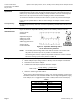

OpenAir™ Non-Spring Return, 24 Vac, Floating Control, Rotary, Electric Damper Actuator Technical Instructions
Document No. 155-188P25
May 22, 2014
Siemens Industry, Inc. Page 5
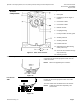
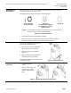
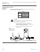
Actuator
Components
Figure 11. Parts of the Actuator.
Legend
1. Base plate
2. Positioning scale for angle of
rotation
3. Connection cables
4. Connection cables
5. Manual override
6. Coupling bushing
7. Factory installed 1/2-inch guide
8. Auxiliary switch A
9. Auxiliary switch B
10. Position indicator
11. Adjustment lever with locking
screw (4 mm hex)
12. Set screw for mechanical range
stop (4 mm hex)
13. Mounting bracket
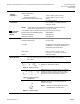
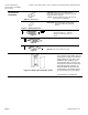
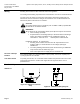
Terminal Strip
Figure 12.
GDE131.1T: The GDE131.1T uses a Terminal Strip
connection for connection purposes rather than the
cable connection.
NOTE: Wires are supplied by the customer.
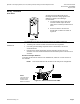
Post Header
AMP
Figure 13.
GDE131.1N: The GDE131.1N model uses a Post
Header for connection purposes rather than cable
connections.
The Post Header has two identical sets of contacts.
NOTE: Cables are purchased separately. See
Accessories.