
Data Sheet for Product


Technical Instructions OpenAir™ Non-Spring Return, 24 Vac, Floating Control, Rotary Electric Damper Actuator
Document No. 155-188P25
May 22, 2014
Page 6 Siemens Industry, Inc.
Operation
A floating control signal controls the damper actuator. The actuator’s angle of rotation is
proportional to the length of time the signal is applied. A 24 Vac control signal to wires 1
and 6 (G-Y1) causes the actuator coupling to rotate clockwise. A 24 Vac control signal to
wires 1 and 7 (G-Y2) causes the actuator coupling to rotate counterclockwise.
To reverse the direction of rotation, the wires 6 and 7 (Y1 and Y2) can be interchanged.
In the event of a power failure or with no control voltage, the damper actuator holds its
position.
Life expectancy
An improperly tuned loop will cause excessive repositioning that will shorten the life of the
actuator.
Auxiliary switches
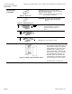
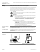
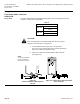
XFigure 13X shows the adjustable switching values for the auxiliary switches A and B.
GDE/GLB136.1P
Actuator Scale:
Clockwise
Adjustment range for
Switches A and B
Setting interval: 5°
Switching hysteresis: 2°
Actuator Scale:
Counterclockwise
Figure 14. Adjustable Switching Values
for the Dual Auxiliary Switches.
NOTE: The auxiliary switch setting shafts rotate with the actuator. The scale is valid
only when the actuator is in the "0" position on clockwise motion.
Use the long arm of the
† to point to the position of switch A. Use the narrower
tab on the red ring to point to the position of switch B.
Sizing
The type of actuator required depends on several factors.
1. Obtain damper torque ratings (ft-lb/ft
P
2
P
or Nm/mP
2
P
) from the damper manufacturer.
2. Determine the area of the damper.
3. Calculate the total torque required to move the damper:
Total Torque =
SF
ea Damper Ar
ing Torque Rat
1
×
4. Select the actuator type from Table 2.
P
1
P
Safety Factor: When determining the torque of an actuator required, a safety factor
should be included for unaccountable variables such as slight misalignments, aging
of the damper, etc. A suggested safety factor is 0.80 (or 80% of the rated torque).
Table 2.
Total Torque
Actuator
<44 lb-in (5 Nm)
GDE13x
<88 lb-in (10 Nm)
GLB13x
<132 lb-in (15 Nm)
GEB13x
<221 lb-in (25 Nm)
GBB13x
<310 lb-in (35 Nm)
GIB13x