
Data Sheet for Product


OpenAir™ Non-Spring Return, 24 Vac, Floating Control, Rotary, Electric Damper Actuator Technical Instructions
Document No. 155-188P25
May 22, 2014
Siemens Industry, Inc. Page 9
Wiring , Continued
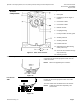
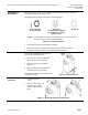
Strain Relief
Figure 20.
Securing the wires/cabling will prevent
breakage and ensure strong signals to the
GDE131.1T model. The following is
recommended:
1. The open bracket to the right of the
actuator terminal strip is the strain
relief for the customer provided control
wires.
2. Secure the wires to the actuator
bracket with a cable tie as shown in
XFigure 19X.
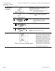
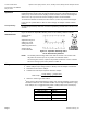
Post Header AMP
GDE131.1N
The GDE131.1N has two sets of identical contacts as shown in
X
Figure 20
X
.
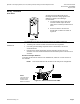
• All wiring must conform to NEC and local codes and regulations.
• Use earth ground isolating step-down Class 2 transformers. Do not use
autotransformers.
• Determine the supply transformer rating by summing the total VA of all
actuators used. It is recommended that one transformer power no more than 12
actuators.
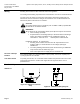
Direction of Damper Rotation
To change the direction of rotation of the GDE131.1N, switch the Y1 and Y2 wires at
the controller.
NOTE: This rotation will affect all actuators in the daisy chain configuration.
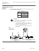
Figure 21. GDE131.1N Post Header AMP.
NOTE:
You must select
either the top 3
contacts or the
bottom 3 contacts.