
Data Sheet for Product


Technical Instructions TH 188 Unit Mounted Thermostat
Document Number 155-064P25
February 3, 2022
Page 6 Siemens Industry, Inc.
Calibration,
continued
Heat-Cool Thermostat
Changeover
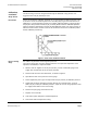
See Table 1 for air pressures and changeover pressures.
The changeover is a factory adjustment; it is sealed with thread locker and does not
require field adjustment. If for some reason this adjustment is disturbed, re-adjust as
follows: (See Figure 4)
1. Supply the thermostat with an air supply equal to the appropriate changeover
pressure.
2. With the exhaust adjustment (center screw) backed out several turns, turn the
switch spring adjustment (outer screw) down snug, and then back off, until air can
be heard bleeding out.
3. Turn the exhaust adjustment down snug and back off approximately 1/8 turn.
4. Seal both screws with thread locker to prevent further movement.
Figure 4. Heating/Cooling Changeover.
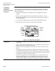
Installation
• A mounting bracket (188-077) is included for mounting the thermostat within the
various units.
• Figure 5 shows a typical installation where the mounting bracket is fastened to the
partition with two sheet metal screws (034-257).
• Mount the remote sensing bulb in the air stream of the return air (near the inlet of
the fan).
• Avoid metal-to-metal contact between the bulb and unit to prevent the soft copper
sensing bulb wearing through due to the rubbing action caused by the unit vibrating.
• Use the adhesive backed cable clip (141-311) supplied with the thermostat to fasten
the capillary and/or bulb in the return air stream.
• If there is not enough room to mount the thermostat in a convenient location, or if
the set point dial must be in the same compartment as the fan switch, order an
extension shaft kit (188-101). The thermostat may be mounted in any convenient
location within the eight-inch length of the shaft extension cable shown in Figure 6.