Technical Bulletin Document No. 155-244P25 TB 237 Rev. 2, December, 2001 PowersTM Controls Accessories for Installing TH 192, TH 194 or Free Energy Band™ TH 193 HC Room Thermostats Purpose This technical bulletin covers installation instructions for all terminal kits and mounting of all TH 192, TH 193 and TH 194 room thermostats. Description The TH 192, TH 193 and TH 194 thermostats are rectangular, 3-11/32 inch × 2-3/16 inch (8.5 cm × 5.6 cm) and may be mounted either horizontally or vertically.
Technical Bulletin Document Number 155-244P25 Rev. 2, December 2001 Accessories for Installing TH 192, TH 194 or Free Energy Band TH 193 HC Room Thermostats Product Numbers, Continued Kit No. Description Used For Figure 192-600 1/4-in. (4 mm) Polyethylene Tubing Kit 8 ft. (2.4 m) Twin (2-Pipe) Finished Wall Sheathing Material 12, 20 192-601 5/32-in. (4 mm) Polyethylene Tubing Kit 8 ft. (2.4 m) Triple (3-Pipe) Finished Wall Sheathing Material 12, 20 192-750 5/32-in.
Accessories for Installing TH 192, TH 194 or Free Energy Band TH 193 HC Room Thermostats Technical Bulletin Document Number 155-244P25 Rev. 2, December, 2001 Product Numbers, Continued Kit No. 192-307 Description Used For Electrical Box, Desert Beige Adapter Base Electrical Box Installation Figure Illustration 7, 21 192-307W Electrical Box, White Adapter Base 192-308 Adapter Frame, Desert Beige Covering up oversized holes, paint lines, broken walls, spots, etc.
Technical Bulletin Document Number 155-244P25 Rev. 2, December 2001 Accessories for Installing TH 192, TH 194 or Free Energy Band TH 193 HC Room Thermostats Installation In New Construction, Continued Figure 2. In Plaster Walls Use Wall Box Kits No. 192-478, 192-498, 192-480, or 192-499. Figure 3. In Block Walls Use Wall Box Kit No. 192478, 192-498, 192-480, or 192-499 After Removing the Mounting Plate. Page 4 Figure 4. For Hollow Walls Use Tubing Terminal Kit No. 192-481. Siemens Industry, Inc.
Accessories for Installing TH 192, TH 194 or Free Energy Band TH 193 HC Room Thermostats Technical Bulletin Document Number 155-244P25 Rev. 2, December, 2001 Installation of The thermostat can be vertically mounted to the wall box kits or to the wall using various TH 192. TH 193, and tubing terminal kits. A typical installation procedure consists of the following steps: TH 194 Thermostats General 1.
Technical Bulletin Document Number 155-244P25 Rev. 2, December 2001 Accessories for Installing TH 192, TH 194 or Free Energy Band TH 193 HC Room Thermostats Installation of TH 192, TH 193, and TH 194 Thermostats General, Continued 4. Install the wall plate on the wall box using the screws furnished with the instrument. Note that the wall plate has key slotted holes to allow insertion of the screws prior to installation of the wall plate and also to allow leveling of the wall plate. 5.
Accessories for Installing TH 192, TH 194 or Free Energy Band TH 193 HC Room Thermostats Disassembly Technical Bulletin Document Number 155-244P25 Rev. 2, December, 2001 When removing the thermostat from the wall plate, hold the thermostat firmly at the top and bottom and start to pull the thermostat from the wall plate. At the same time, us a screwdriver to pry the wall plate latch arm away from the thermostat chassis to release it.
Technical Bulletin Document Number 155-244P25 Rev. 2, December 2001 Accessories for Installing TH 192, TH 194 or Free Energy Band TH 193 HC Room Thermostats Installation in Existing Construction Concealed Piping, Continued Figure 6. Mounting Wall Plate and Thermostat with Kit Nos. 192-481 and 192-685. Exposed Piping • For exposed piping installations, use Kit No. 192-479 and adapter Kit No. 192-483. See Figure 7.
Accessories for Installing TH 192, TH 194 or Free Energy Band TH 193 HC Room Thermostats Technical Bulletin Document Number 155-244P25 Rev. 2, December, 2001 Installation in Existing Construction Exposed Piping, Continued Figure 7. Exposed Piping Installation Using Kits No. 192-479 and 192-483. TH 192 DNV (or Three-pipe) Thermostats (See Figure 8) The installation of a DNV Thermostat is identical to other thermostats except that a third line, "R2," is required.
Technical Bulletin Document Number 155-244P25 Rev. 2, December 2001 Accessories for Installing TH 192, TH 194 or Free Energy Band TH 193 HC Room Thermostats Installation in Existing Construction Exposed Piping, Continued Figure 8. Installing "DNV" Thermostat Using No. 192-498 or 192-499 Wall Box Terminal. Dual Box Installation Occasionally, two devices, thermostats, hygrostats, or transmitters will be located together.
Accessories for Installing TH 192, TH 194 or Free Energy Band TH 193 HC Room Thermostats Technical Bulletin Document Number 155-244P25 Rev. 2, December, 2001 Drywall Installation The roughing-in procedure depends on whether or not drywall is up at installation time. Rough-in before drywall is up If roughing-in can be done before drywall is up, see Figure 10. Figure 10. Mounting Wall Plate and Instrument with Bracket Mounting Kit.
Technical Bulletin Document Number 155-244P25 Rev. 2, December 2001 Accessories for Installing TH 192, TH 194 or Free Energy Band TH 193 HC Room Thermostats Drywall Installation, Continued Rough-in before drywall is up Figure 11. Drywall Mounting Bracket Positions. A typical installation procedure consists of the following steps: 1. Attach the drywall mounting bracket (D) to the stud per the position selected at the desired location.
Accessories for Installing TH 192, TH 194 or Free Energy Band TH 193 HC Room Thermostats Drywall Installation, Continued Technical Bulletin Document Number 155-244P25 Rev. 2, December, 2001 7. Install the wall plate on the bracket (D) using the screws furnished with the instrument. Note that the wall plate has key slotted holes to allow insertion of the screws prior to installation of the wall plate and also to allow leveling of the wall plate. 8. Attach the thermostat.
Technical Bulletin Document Number 155-244P25 Rev. 2, December 2001 Drywall Installation, continued Installation after drywall is up Accessories for Installing TH 192, TH 194 or Free Energy Band TH 193 HC Room Thermostats A typical installation procedure consists of the following steps: 1. Place the template (D) on the wall at the desired location. The template has adhesive on the back, protected by paper; remove the paper backing and make sure the template is level before it sticks to the wall surface.
Accessories for Installing TH 192, TH 194 or Free Energy Band TH 193 HC Room Thermostats Technical Bulletin Document Number 155-244P25 Rev. 2, December, 2001 Mounting and Installation Kits Figure 14. Terminal Kit Nos. 192-478, 192-480, 192-498, and 192-499. Kit No. 192-478 192-498 192-480 192-499 Type of Terminal Type of System Wall Box with 8-foot (2.4 m) Copper Tubing 2-Pipe Wall Box with 8-foot (2.4 m) 1/4-in. (6.
Technical Bulletin Document Number 155-244P25 Rev. 2, December 2001 Accessories for Installing TH 192, TH 194 or Free Energy Band TH 193 HC Room Thermostats Mounting and Installation Kits, Continued Figure 15. Tubing Kit No. 192-481 (10/Kit) and 192-505 (10/Kit). Item No. Part Number 1 163-463 2 — 3 192-513 4 — 5 Quantity/Kit Description Kit 192-481 Kit 192-505 Connecting Tube -- 4 inch (101.6 mm) (2 required) 40 40 Tube Retainer (4 req'd) Kit No.
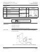
Accessories for Installing TH 192, TH 194 or Free Energy Band TH 193 HC Room Thermostats Technical Bulletin Document Number 155-244P25 Rev. 2, December, 2001 Mounting and Installation Kits, Continued Dimensions in inches (mm) Figure 17. Panel Mounting or Standard Mullion Cut-out for TH 192, TH 193, and TH 194 Thermostats. Figure 18. Plug-in Adapters. Item No.
Technical Bulletin Document Number 155-244P25 Rev. 2, December 2001 Replacing O-rings Accessories for Installing TH 192, TH 194 or Free Energy Band TH 193 HC Room Thermostats If leaks are detected around the O-rings, new rings should be installed. To install, insert a pencil in the O-ring, pry out and replace with a new ring. It is not necessary to remove the wall plate. NOTE: To facilitate installation, wet or moisten the new ring when installing.
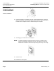
Accessories for Installing TH 192, TH 194 or Free Energy Band TH 193 HC Room Thermostats Technical Bulletin Document Number 155-244P25 Rev. 2, December, 2001 Figure 20. Tubing Kit Nos. 192-600, 192-601, 192-750, 192-753, and 192-755. Item No. Kit Number 1 163-463 2 — 3 192-513 4 Description Quantity / Kit Kit Kit 192-750 192-753 2-Pipe 3-Pipe Kit 192-600 2-Pipe Kit 192-601 3-Pipe Connecting Tube – 4-inch (101.6 mm) 2 3 2 3 2 Tube Retainer Kit No.
Technical Bulletin Document Number 155-244P25 Rev. 2, December 2001 Accessories for Installing TH 192, TH 194 or Free Energy Band TH 193 HC Room Thermostats Figure 21. Adapter Kit. *Kit No.