
Data Sheet for Product

Pressure Independent Control Series Two-Way Valve Bodies Technical Instructions
Document No. 155-774
May 18, 2021
Siemens Industry, Inc. Page 5
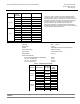
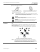
To change the valve flow setting, see Steps 2, 3, and 4 below (Flow setting scales are in
gallons per minute [gpm] on all valves):
1. On 1/2- to 1-1/4-inch valves, loosen
the brass knurled nut. On 1-1/2 and 2-
inch valves, loosen the valve stem.
2. Adjust the desired dial setting with the white knob.
3. Retighten the brass knurled nut or valve stem by
hand.
NOTE: When tightening the knurled nut on 1/2- to 1-1/4-inch valves, some force is
required to reach the required physical stop; approximately an additional 1/2 to
3/4 extra turn after initial “finger tight” resistance is felt.
CAUTION:
On 1-1/2- and 2-inch valves, do NOT use tools to tighten the valve stem.
Hand-tighten only or damage will occur.
CAUTION:
Do NOT rotate the actuator on the valve once the actuator and valve stem
are connected. Doing so will inadvertently adjust the flow setting of the
valve or damage the stem.
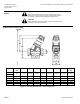
Mounting and
Installation
Install the valve so the flow follows the direction of the arrow indicated on the valve
body.
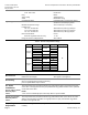
For best performance, install the valve assembly with the actuator above the valve
body. The valve and actuator can be installed in any position between vertical and
horizontal. See Figure 1.
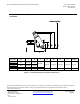
Do not install the valve assembly with the actuator below horizontal or upside down.
Figure 1. Recommended Installation Orientations.
NOTE: Allow enough space for servicing the valve and actuator. Instructions for
field mounting an actuator, wiring diagrams, and start-up are covered in the
SSD Series Electronic Valve Actuator Installation Instructions (129-540) and
SAY Electronic Valve Actuators Installation Instructions (129-583).