
Installation Instructions

Installation Instructions
Document No. 129-540
May 9, 2019
SSD Series Electronic Valve Actuator
(For use with 1/2-Inch to 1-1/4-inch Pressure Independent Control Valves)
Item No: 129-540, Rev EA Page 1 of 6
Product Description
The SSD Actuator requires a 24 Volt power supply and
a 0 to 10 Vdc or floating control signal to control the
1/2-inch to 1-1/4-inch Siemens 599 Series Pressure
Independent Control Valves with a 1/10-inch (2.5 mm),
1/5-inch (5 mm), or 7/32-inch (5.5 mm) stroke.
Contents
SSD61U, SSD81U:
• One actuator
• One terminal plug
• One terminal connector
SSD61.5U, SSD81.5U:
• One actuator
Product Numbers
Product
Number
Description
Actuator
Code
SSD61U
0 to 10 Vdc control, NSR
231
SSD81U
Floating control, NSR
230
SSD61.5U
0 to 10Vdc control, SR
233
SSD81.5U
Floating control, SR
232
Warning/Caution Notations
WARNING:
Personal injury/loss of life
may occur if you do not follow
a procedure as specified.
CAUTION:
Equipment damage may
occur if you do not follow a
procedure as specified.
Required Tools
• 3 mm hex key
• Small flat-blade screwdriver
• Small, Phillips screwdriver
• Wire stripper
Expected Installation Time
20 minutes
Prerequisites
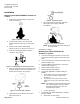
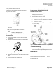
Figure 1. Acceptable Mounting Positions.
NOTE: Vertical mounting position recommended.
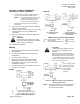
Figure 2. Acceptable Mounting Position with Valve.
NOTE: Vertical mounting is recommended.
WARNINGS:
• If mounting the actuator to a valve
already in line, either close the shut-off
valves in the piping (upstream first,
then downstream), or switch off the
pump to allow the differential pressure
in the valve to drop.
• Disconnect the controller power before
replacing the actuator. See Removing
an SSD61.5U/SSD81.5U Actuator
from a Valve.
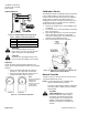
CAUTION:
• Before applying power, make certain a
valve is connected to the actuator.
• If applying power to the actuator when
a valve is not connected, the actuator
will respond to a control signal and the
shaft will extend until it reaches its
maximum end stop. Thereafter, it will
not respond to any signal.
• If this occurs, disconnect the power.
Insert a 3mm hex key into the manual
override feature and retract the
actuator to the zero position. Verify the
actuator shaft is retracted completely.
See Figure 15.
• Connect a valve to the actuator,
reapply the power, and the actuator
will return to normal operation.