
Installation Instructions

Installation Instructions
Document No. 129-540
May 9, 2019
Page 2 of 6 Siemens Industry, Inc.
Installation
Mounting an SSD61U/SSD81U Actuator on
a Valve
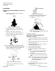
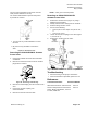
1. Remove the protective plastic cap from the
valve. See Figure 3.
Figure 3. Remove Plastic Cap.
2. Using a 3 mm hex key, turn the manual-
position indicator on the top of the actuator
to 0.
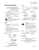
3. Attach the wires to the terminal plug.
(Reference Wiring, See Figure 8 and Figure 12.)
4. Insert the terminal plug into the terminal
connector. See Figure 4.
Figure 4. Terminal Plug and Terminal Connector.
5. Place the terminal connector and plug into the
actuator, fitting the nut into the recess in the
bottom of the actuator. See Figure 5.
Figure 5. Insert Terminal Connector.
6. Tighten the screw to hold the connector in
place. See Figure 6.
Figure 6. Tighten the Screw.
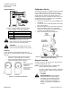
7. Place the actuator on the valve and firmly
hand-tighten the coupling clockwise.
See Figure 7.
Figure 7. Hand-Tighten Clockwise.
NOTE: Be sure the visual position indicator is
at the 0 position.
Installation is complete.
Mounting an SSD61.5U/SSD81.5U
Actuator on a Valve
1. If you are attaching the actuator to a new valve,
remove the protective plastic cap from the valve
stem.
2. Use a 3 mm hex key to retract the actuator to the
0 position (Figure 15).
3. Using a Phillips head screwdriver, remove the
terminal cover (Figure 17).
4. Remove wiring retention screw.
5. Remove plenum cable adapter.
6. For plenum applications, complete wiring as
follows:
a. Route cable through plenum cable adapter so
there is sufficient cable to complete wiring
terminations.
b. Insert plenum cable adapter into flex conduit
adapter and secure in place with wiring retention
screw.
NOTE: Insert wiring retention screw in hole of the
flex conduit adapter. (The hole nearest
the wiring terminals is to secure the
terminal cover in place.)
c. Continue with Step 8.
7. For 3/8-inch flex conduit applications, complete
wiring as follows:
a. Discard plenum cable adapter.