
Installation Instructions

Document No. 129-540
Installation Instructions
May 9, 2019
Siemens Industry, Inc. Page 3 of 6
Mounting an SSD61.5U/SSD81.5U
Actuator on a Valve, Continued
b. Insert flex conduit into flex conduit adapter and
secure in place with wiring retention screw.
NOTE: Insert wiring retention screw in hole of
the flex conduit adapter. (The hole
nearest the wiring terminals is to
secure the terminal cover in place.)
c. Route wiring through flex conduit for wiring
terminations.
8. Connect wires to wiring terminals per the Wiring
section of this document.
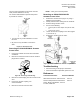
9. Secure the terminal cover in place over the wiring
terminals (Figure 17) using a Phillips head
screwdriver,
10. Place the actuator on the valve and firmly hand-
tighten Figure 7.
CAUTION:
Hand-tighten the actuator to the valve.
The use of tools to tighten the assembly
together will cause damage.
The installation is complete.
Wiring
• All wiring must conform to NEC and local codes
and regulations.
• Use earth ground isolating step-down Class 2
transformers.
• Do not use autotransformers.
• Determine the supply transformer rating by
summing the total VA of all actuators used.
• The maximum rating for a Class 2 step-down
transformer is 100 VA.
• It is recommended that one transformer power no
more than 10 actuators.
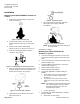
SSD81U
G
24 Vac Operating Voltage
Y1
Output shaft extends, valve opens
Y2
Output shaft retracts, valve closes
Figure 8. SSD81U Wiring Diagram.
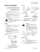
SSD81.5U
Figure 9.
For Non-Triac Driven
Controllers.
Figure 10.
For Triac Driven
Controllers, (TEC, DXR,
and Others).
SSD81.5U Floating Control SR Hot-Switch.
G, G0: 24 Vac operating voltage Y1 Extends actuator
G System neutral shaft
G0 System potential (switched) Y2 Retracts actuator
shaft
CAUTION:
Terminals must be properly wired for
correct function and full life of the
actuator.
Because the triacs on TECs and DXRs
always switch hot power, add a 1000 Ohm
2-Watt resistor across each of the binary
(Y1, Y2) outputs (see Figure 10). The two
resistors must be used for all hot-switching
triacs not just TEC and DXR.
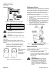
G, G0:
24 Vac Operating voltage
Y2: Retracts actuator shaft
Y1: Extends actuator shaft
G: System potential
G0: System neutral
(switched)
Figure 11. SSD81.5U Floating Control SR Neutral
Switching Applications.
NOTE: For proper operation, it is recommended no
more than three actuators be assigned to
any single control signal.