
Installation Instructions
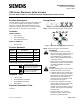

Installation Instructions
Document No. 129-540
May 9, 2019
Page 4 of 6 Siemens Industry, Inc.
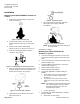
SSD61U/SSD61.5U
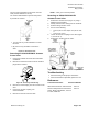
Figure 12. SSD61U/SSD61.5U Wiring Diagram.
Table 1. SSD61U Terminal Designations.
G,G0
24 Vac operating voltage
G
System potential, 24 Vac
G0
System neutral
Y
0 to 10 Vdc control signal
WARNING:
On the SSD61U/SSD61.5U the wire
connection G is 24 Vac, system potential
(HOT), not System neutral (ground).
CAUTION:
G0 and G must be properly wired for the
correct function and full life of the actuator.
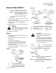
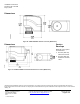
Start Up
Check the wiring and the position indication. See
Figure 13 for referred positions 0 and 1 on the position
indicator.
• When the position indicator disc rotates to
position "1", the output shaft is extended.
• When the position indicator disc is at the "0"
position the output shaft is retracted.
Position 1
Position 0
Figure 13. Visual Position Indication.
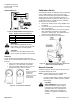
Calibration Stroke
The SSD61.5U writes its calibration stroke parameters
to non-volatile memory on the first start-up of the
actuator. Successive start-ups bypass the calibration
stroke unless the memory is manually cleared. If
installing the actuator on a different valve (such as on
a replacement valve), manually clear the calibration
stroke from memory as follows:
1. Remove the terminal cover using a Phillips head
screwdriver.
2. Locate hole on the circuit board with the shorting
bars. See Figure 14.
3. With power applied to the unit, insert and gently
twist a flat-blade screwdriver to electrically
connect the shorting bars. The SSD61.5U then
performs a new calibration stroke.
4. Secure the terminal cover back in place.
Figure 14. Manually Clearing Calibration Stroke from
SSD61.5U Non-volatile Memory.
Manual Override
A 3 mm hex key can be used to move the actuator to
any position between 0 and 1.
NOTE: A control signal from the controller takes
priority in determining the position.
To retain the manually set position, unplug the
connecting cable or switch off power and the
control signal.
CAUTION:
SSD61U/SSD61.5U: If an override is
performed while the power supply is
connected, the actuator will not track
accurately when the control signal is
applied. A short power off/power on
sequence is required to recalibrate the
actuator.
Note:
The 0 and 1 position
markings are
intended for
reference only and
not for stroke
measurement.