
Installation Instructions

Document No. 129-540
Installation Instructions
May 9, 2019
Siemens Industry, Inc. Page 5 of 6
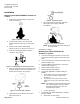
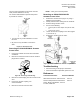
Turn the wrench clockwise to extend the actuator
shaft (counterclockwise to retract).
The actuator will maintain its position until power
is provided or restored.
• (A) Turn hex key counterclockwise to retract
the shaft.
• (B) Turn hex key clockwise to extend the
shaft.
Figure 15. Manual Override.
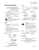
Removing an SSD61U/SSD81U Actuator
from a Valve
1. Loosen the terminal connector with a flat-blade
screwdriver.
2. Remove the terminal connector and the terminal
plug from the actuator.
Figure 16. Removing Terminal Plug.
3. Remove the terminal plug from the connector and
save.
4. Loosen the actuator coupling, turn
counterclockwise.
5. Remove the actuator from the valve.
NOTE: Valve goes to closed position.
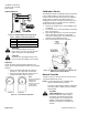
Removing an SSD61.5U/SSD81.5U
Actuator from a Valve
1. Remove the terminal cover (Figure 17) using a
Phillips head screwdriver.
2. Identify and disconnect wiring from the terminals.
3. Remove wiring retention screw.
4. Do one of the following:
• Remove plenum cable adapter and plenum cable;
or
• Remove flex conduit.
5. Loosen the actuator coupling on the valve (Figure
7, reverse No. 2).
6. Remove the actuator from the valve.
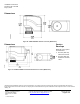
Figure 17. SSD61.5U/SSD81.5U Actuator Components.
Troubleshooting
• Check the wiring for the proper connections.
• If actuator becomes inoperable, replace the unit.
References
Technical Instructions Document Number
SSD Series Electronic Valve Actuator 155-773
Pressure Independent Control Series 155-774
2-Way, Brass Valve Bodies, 1/2-inch
to 2-inch, ANSI 250