
Data Sheet for Product

Technical Instructions Pressure Independent Control
Document No. 155-773 SSD Series Electronic Valve Actuators
May 8, 2019
Page 4 Siemens Industry, Inc.
Operation,
Continued
SSD81U
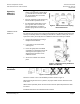
A 24 Vac control signal to terminal Y1 extends the actuator shaft proportionately to the
length of time the signal is applied.
A 24 Vac control signal to terminal Y2 retracts the actuator shaft proportionately to the
length of time the signal is applied.
In the event of a power failure with no control voltage, the non-spring return SSD81U will
hold its last position.
The SSD81U floating actuator does not self-calibrate.
SSD61U
The stroke travel on the SSD61U is proportional to the control signal Y. A zero voltage
control signal retracts the stem and returns the valve to its normal position. With no
supply voltage, the SSD61U actuator maintains its last position.
Calibration Stroke
The SSD61U is equipped with a microprocessor to control the valve stroke length. The
actuator will complete a stroke calibration each time the power supply voltage is
connected.
CAUTION:
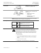
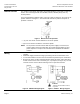
Whenever the SSD61U runs a self-calibration routine (Valve stroke 0
Max. stroke Setpoint), do not manually intervene in this process. See
Figure 3.
Figure 3. SSD61U Self-Calibration.
NOTE: Correct calibration is possible only with valve strokes >1.5 mm. For valve
strokes <1.5 mm, the actuator/valve combination locks after three failed
calibration attempts.
SSDx1.5U
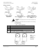
For the SSD81.5U, a 24 Vac control signal to terminal Y1 extends the actuator shaft
proportionately to the length of time the signal is applied.
A 24 Vac control signal to terminal Y2 retracts the actuator shaft proportionately to the
length of time the signal is applied.
The stroke of the SSD61.5U is proportional to the control signal on terminal Y. A 0 Vdc
control signal retracts the stem and returns the valve to its normal position.
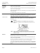
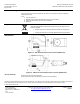
In the event of a power failure, the SSDx1.5U returns to the stem up, or normal position.
The SSDx1.5U includes an electronic return mechanism that functions as follows. See
Figure 4.