
Data Sheet for Product

Pressure Independent Control Technical Instructions
SSD Series Electronic Valve Actuators Document No. 155-773
May 8, 2019
Siemens Industry, Inc. Page 5
Operation,
SSDx1.5U
Continued
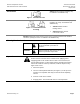
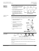
• At power-up (t
0
), a capacitor must
charge to its maximum capacity (Max,
t
c
). This will take a maximum of 180
sec, during which time no actuator
movement occurs.
• Once the capacitor is fully charged (t
c
),
normal actuator operation occurs.
• If a subsequent power failure occurs
(tn) of greater than 5 seconds, the
capacitor discharges (t
d
) and the
actuator spring returns to stem up 0
position.
Figure 4. SSDx1.5U Electronic Spring
Return Mechanism.
Calibration Stroke
SSD61.5U
The SSD61.5U writes its calibration stroke parameters to nonvolatile memory on the
first startup of the actuator. Successive startups bypass the calibration stroke unless the
memory is manually cleared. If installing the actuator on a different valve (such as on a
replacement valve), manually clear the calibration stroke from memory as follows:
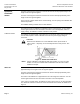
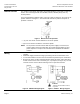
1. Remove the terminal cover using a
Phillips head screwdriver.
2. Locate hole on the circuit board
shorting bars.
3. Insert and gently twist a flat-blade
screwdriver to electrically connect the
shorting bars (see Figure 5). The
SSD61.5U then performs a new
calibration stroke.
4. Secure the terminal cover back in
place.
Figure 5. Manually Clearing Calibration
Stroke from Memory.
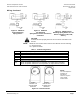
Mounting and
Installation
Figure 6. Mounting Positions.
Mount the actuator in one of the allowable positions shown in Figure 6.
When mounting the actuator in a plenum, the proper cable must be attached to meet
local codes.
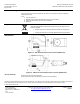
Allow 8 inches (200 mm) above the actuator and 8 inches (200 mm) behind the cable
for service.
Installation instructions are included with the actuator.