
Data Sheet for Product

Technical Instructions Pressure Independent Control
Document No. 155-773 SSD Series Electronic Valve Actuators
May 8, 2019
Page 6 Siemens Industry, Inc.
Manual Override
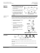
The actuator can be driven manually to any position between 0 and 1 with a 3 mm hex
wrench. The control signal from the controller, however, will take priority over any
manual position.
For manual positioning (without power), insert the 3 mm hex wrench in the center of the
position indicator. See Figure 7. The actuator will maintain its position until power is
provided or restored.
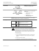
Figure 7. Manual Override Operation.
• (A) Turn hex wrench counterclockwise to retract the spindle.
• (B) Turn hex wrench clockwise to extend the spindle.
NOTE: Do not perform manual override while the power supply is connected; the
actuator will not track accurately when the control signal is applied. A short
power off/power on sequence is recommended to recalibrate the SSD61U
actuator.
Wiring
• Do not use autotransformers. Use earth ground isolating step-down Class 2 power
supplies.
• Determine supply transformer rating by summing total VA of all actuators used.
• It is recommended that no more than 10 actuators be powered by one transformer.
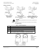
• Because the triacs on TECs and DXRs always switch hot power, add a 1000 Ohm
2-Watt resistor across each of the binary (Y1, Y2) outputs (see Figure 12). The two
resistors must be used for all hot-switching triacs not just TEC and DXR.
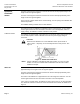
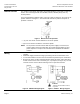
Figure 8. SSD81U Wiring Diagram.
WARNING:
Terminal connection G0 is Common,
not ground.
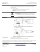
Figure 9. SSD61… Wiring Diagram.