
Data Sheet for Product

Pressure Independent Control Technical Instructions
SSD Series Electronic Valve Actuators Document No. 155-773
May 8, 2019
Siemens Industry, Inc. Page 7
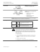
Wiring, Continued
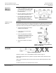
Figure 10. SSD81.5U
Neutral Switching
Spring Return.
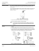
Figure 11. SSD81.5U
Hot Switching
Spring Return for Non-Triac Driven
Controllers.
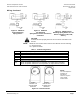
Figure 12. SSD81.51U Hot
Switching Spring Return for Triac
Driven Controllers (TEC, DXR,
Others).
CAUTION:
Terminals must be properly wired for correct function and full life of the
actuator.
NOTE: SSD81.5U can be wired either neutral or hot switched. For hot switching:
G = System Neutral
G0 = System Potential
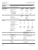
Table 2. Terminal Designations.
G, G0
24 Vac Operating Voltage
G
System Potential
G0
System Neutral
Y
0 to 10 Vdc Control Signal
Y1
Output shaft extends
Y2
Output shaft retracts
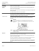
Start-
Up
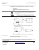
Check the wiring and the position indication.
When the position indicator is in the 1 position, the output shaft is extended.
When the position indicator is on the 0 position, the output shaft is retracted.
Position Position
indicator at 1 indicator at 0
Actuator Stem Actuator Stem
Extended Retracted
Figure 13. Position Indicator.
NOTE:
The 1 and 0 position
markings are
intended for
reference only and
not for stroke
measurement.