
Data Sheet for Product

599 Series Zone Valve Actuator Technical Instructions
SF Series Electronic Valve Actuator Document No. 155-321P25
2-position Control April 1, 2021
Siemens Industry, Inc. Page 3
Mounting and
Installation
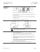
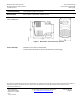
Figure 1. Mounting Position.
• Mount the actuator in one of the allowable positions shown in Figure 1.
• When mounting the actuator in a plenum, the proper cable must be attached
to meet local codes.
• Allow 8 inches (200 mm) above the actuator and 8 inches (200 mm) behind
the cable for service.
• Installation Instructions are included with the actuator.
Wiring
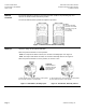
Figure 2.
24 Vac Wiring Diagram.
Figure 3.
120 Vac Wring Diagram.
WARNING:
Wire connection, G is Hot, not ground.
• Do not use autotransformers.
• Use earth-ground isolating, step-down, Class 2, power supplies.
• Determine supply transformer rating by summing total VA of all actuators
used.
• SFA71U/SFP71U 24 Vac actuators: Wiring connection is inside the actuator
housing (remove housing top for access). The actuator lead length is 10
inches (254 mm).
• SFA11U/SFP11U 120 Vac actuators: Wiring connection requires junction box
and flex conduit no further than 15 inches (381 mm) from the actuator. The
actuator lead length is 18 inches (457 mm).
NOTE: One transformer should power no more than 10 actuators.